Translate

2025年8月29日星期五

This article explains how to adjust the wear pads of the extended bucket of a JCB backhoe loader


Preparing the Cab Frame Aperture

If damp or wet, dry the aperture area using a hot air gun

(sourced locally).

Use 'Active Wipe 205' to thoroughly clean and 'prime'

the trimmed sealant. Use a lint free cloth to apply the

'Active Wipe 205', allow 5 minutes flash off (drying)

time.

Note: Do not use any other type of cleaning fluids, otherwise

they may be absorbed into the old sealant and ultimately

prevent the new glass from bonding.

Direct Glazing (cont'd)

Preparing the New Glass

JCB Electronic Service Tool Diagnostic Kit High Quality

! CAUTION

The laminated front screen must be handled with extra

care to prevent breakage. Wherever possible, store and

handle it in a vertical attitude. When placing or lifting the

screen in a horizontal attitude it must be supported over

its whole area, not just at the edges.

BF 1-8

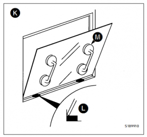
1 Make sure that the new glass correctly fits the frame

aperture K.

a Put two spacer blocks L onto the bottom part of the

frame aperture.

b Install the new glass on the spacer blocks - ALWAYS

USE GLASS LIFTERS M (see Service Tools). Check

that there is an equal sized gap all round the edge of

the glass.

Note: The spacer blocks are rectangular in section to give

two common gap widths. If necessary they can be trimmed

to a smaller size to give an equal sized gap around the glass.

IMPORTANT: The glass edges MUST NOT touch the frame,

otherwise movement of the frame will chip and eventually

break the newly installed glass.

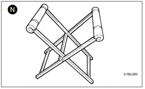
2  After checking for size, remove the new glass and place

it on a purpose made glass stand N (see Service

Tools).

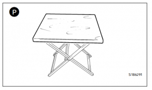
Small panes of glass will need locating on a 600 x 700 mm x

15 to 19 mm thick plywood board P (sourced locally to fit

the glass stand N). It is recommended that an access hole is

cut in the board to accommodate the glass lifter, making it

easier and safer to handle small panes of glass. The board

should be covered with felt or carpet to give an anti-scratch

surface. Resting the glass on four spacer blocks will ensure

clearance of the cartridge nozzle tip during application of the

polyurethane sealant.

3  Make sure the glass is positioned on the stand the

correct way up (i.e. with the black ceramic ink band

upwards) ready for application of primer etc.

4 a Use 'Active Wipe 205' to thoroughly clean and

'prime' the black ceramic ink band printed on the

glass (see Note 1). Use a lint free cloth to apply the

'Active Wipe 205', allow 5 minutes flash off (drying)

time.

Note 1: Do not touch the glass after cleaning with the

'Active Wipe 205'.

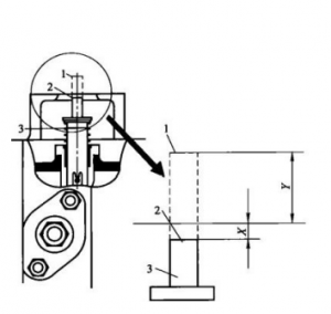
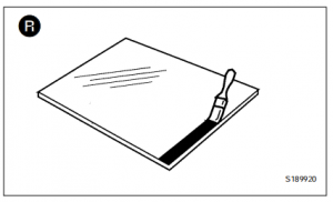
b If the glass does not have a black ceramic ink band,

paint a band on the glass using 'Black Primer 206J'.

The band should be approximately 25mm (1in) wide,

and the edge should be a neat straight line as shown

at R

06.2025 JCB ServiceMaster 4 v25.3.3 Diagnostic Software with SW Files Download and installatiom

Direct Glazing (cont'd)

Preparing the New Glass (cont'd)

5  Install the Ultra Fast Adhesive cartridge (see Sealing

and Retaining Compounds and Note 2 below) into a

suitable applicator gun:

a Remove the aluminium disc cover from the base of

the cartridge and discard the 'dessicant capsule'.

b Make sure that the rolled edge of the cartridge is not

damaged - if necessary, the edges should be

pressed flat, otherwise it will be difficult to remove

the cartridge from the applicator gun.

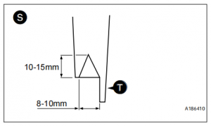
c Pierce the front 'nozzle' end of the cartridge to its

maximum diameter.

d Fit the pre-cut nozzle shown at S.

e Install the cartridge in the applicator gun.

Note 2: Cold material will be very difficult to extrude. The

cartridges must be pre-heated in a special oven (see

Service Tools) for 1 hour to a temperature of 80°C (176°F).

Pre-heating the cartridges makes the adhesive more

workable and also brings the 'curing' time down to 30

minutes.

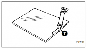
6   Apply the pre-heated adhesive to the glass (do not start

in a corner). Keep the nozzle guide T against the edge

of the glass and make sure that the adhesive forms a

continuous 'pyramid' shape.

Note 3: Once the pre-heated adhesive has been applied to

the glass, install the glass in the aperture as soon as

possible. After approximately 10 minutes the sealant will

form a 'skin', this will prevent the glass from bonding.

7   After applying the adhesive, leave a small amount of

sealant protruding from the nozzle. This will prevent any

adhesive left in the cartridge from 'curing'.

Installing the New Glass

1   Make sure the two spacer blocks are in position (see

step 1 of Preparing the New Glass).

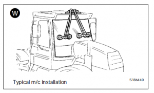
2    Install the glass in the frame aperture:

a ALWAYS use the special lifting tools when moving

the glass. Use a lifting strap to hold large panes of

glass in position as shown W.

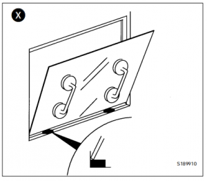
b Sit the bottom edge of the glass on the spacer

blocks as shown X.

c Make sure that the glass is correctly positioned, then

gently press around the edges of the glass and

ensure full adhesive contact is achieved. Do not

press too hard or too much adhesive will squeeze

out.

Direct Glazing (cont'd)

Installing the New Glass (cont'd)

3   Make the inside seal smooth:

a Wearing surgical gloves, dip your finger in a soapy

water solution.

b  Use your finger to make the inside seal smooth.

4    All exposed edges must be sealed using Black

Polyurethane Sealant (see Sealing and Retaining

Compounds).

5    Clean the glass after installation:

IMPORTANT: Use extreme caution when wiping the inside

of the new glass - pushing too hard on the inside of the

glass will affect the integrity of the bonded seal.

a Small amounts of sealant can be cleaned from the

glass using the 'Active Wipe 205'.

b Large amounts of excess sealant should be left to

'cure' (see Note 4) and then cut off with a sharp

knife.

Note 4: On completion of the glass replacement procedures,

the sealant 'curing' time is 30 minutes. This means that the

machine can be driven and used after 30 minutes, but it

MUST NOT be used during the curing period of 30 minutes.

c  Clean the glass using a purpose made glass

cleaner.

6   On completion of the glass installation procedures tidy

the work area:

a Remove ALL broken glass from the cab area.

b Remove the protective covers from the cab seat and

control pedestals.

c Renew all 'warning' and 'information' decals so that

the new installation conforms with the original cab

installation.

JCB Agco SISU Power WinEEM4 – JCB Service Tool 2.8.0

2025年8月27日星期三

This article introduces the maintenance of the DEUTZ FL413F/513 diesel engine body.


The body group is the support of the diesel engine and the installation base for the crankshaft connecting rod mechanism, valve mechanism and other major components of the diesel engine mechanism and system. The diesel engine body group mainly consists of the cylinder block (or engine block, crankcase), cylinder gasket, cylinder head, cylinder liner and oil pan.

2024 Deutz SerDia 4.0 SerDia2010 14.1.9.3 Highest Level 6 Diagnostic Software

(1) Structure of the body The FL413F/513 diesel engine body adopts a gantry structure (as shown in Figure 2-2). This structure has a relatively high body rigidity. The upper part of the V-shaped body is two cylinder liner mounting planes at a 90° angle to each other. The injection pump bracket and fan transmission box are installed in the middle, and the lower part is the oil pan joint surface. The cylinder liner mounting plane is at a 45° angle to the oil pan joint surface. The body is cast from gray alloy cast iron. The hardness is 180~250HB. The center distance between the cylinder liner mounting holes on the cylinder liner mounting plane is 165mm, and the hole diameter is 139mm. Due to the parallel connecting rod mechanism, the left and right cylinder liner mounting holes are not on the same center line and are offset by 29mm.

① The diameter of the bottom hole of the crankcase main bearing is φ 101 (+0.022)mm, and the third cross partition is dedicated to thrust positioning. The main bearing cover is tightened by two M16×1.5mm vertical bolts and two M10mm horizontal bolts at the same time. The main bearing cover is made of QT50-5 ductile iron.

Deutz Diagnostic Tool Communicator for Deutz Engine DECOM Controllers

② A φ22.5mm main oil channel bottom hole is cast in the crankcase, and a φ22mm oil pipe is installed; the main oil channel is connected to the main bearing bottom hole


(2) Characteristics of the engine body The FL413F/513 diesel engine body has the following characteristics.

① High degree of universalization, serialization and standardization. Except for the length, the other structural elements of the models with different cylinder numbers are basically the same.

② Compact structure and small size. The horizontal width of the oil pan joint surface is only 265mm, which is convenient for installation on the equipment.

③ The transmission gearbox and the crankcase are cast as one piece, which increases the overall rigidity of the rear part of the crankcase and the crankcase.

④ In addition to two vertical bolts, the main bearing cover and the engine body are fastened with two horizontal bolts. This better ensures the rigidity of the engine body and helps reduce the noise of the diesel engine.

(3) Main damage modes of the cylinder block The main damage modes of the diesel engine body are:

① Broken connecting rod bolts;

② Deformation, loss of roundness or deterioration of the coaxiality of the main bearing bottom hole due to the burning of the bearing;

③ Deformation or cracking of the cross-partition of the main bearing bottom hole due to overload operation or other factors;

④ Abnormal damage caused by other reasons, etc.

(4) Inspection points of the engine body (crankcase or cylinder block) The engine body of a diesel engine is the basic component of the diesel engine, and all moving parts are installed on it. Therefore, the quality of the engine body directly affects the running stability and reliability of the entire diesel engine. When overhauling a diesel engine, the quality of the engine body should be carefully checked, with a focus on the following parts.

① The quality of the bottom hole of the main bearing of the engine body, that is, check whether the main shaft hole is out of round, whether there are cracks or bearing rotation, and whether the coaxiality of all holes is out of tolerance.

② Whether the engine body water jacket, cross partition, etc. have quality problems such as cracks or looseness.

③ Whether the various installation surfaces (mainly the installation surfaces with the cylinder liner and cylinder head) are deformed or have pits, corrosion spots, etc.

④ Whether the relevant oil channels (such as: the main oil channel of the engine oil or the diesel oil channel of the single pump diesel engine, etc.) are intact. Only when the engine body is checked to confirm that there are no quality problems can it be used again. Otherwise, it should be repaired before use.

(5) Repair method of cracks in the engine block cross-plate When a diesel engine fails due to lack of oil, such as burning bearings or shaft seizure, the bottom hole of the main bearing bearing may be worn out and out of round, deformed or cracked. In this case, the bottom hole of the main bearing needs to be repaired. The repair points are shown in Table 2-1.

Deutz Serpic 2012 EPC Download & Installation Service Finial Version

If the technology is good enough, the best repair method is to use thermal spraying to repair the engine block (cylinder block) because it can completely restore the original standard size and accuracy requirements of the bottom hole of the main bearing of the engine block. A successful case in this regard is the use of thermal spraying to repair the engine blocks of several F12L513 diesel engines. After years of use, no quality problems have occurred in the repaired parts.

Insufficient degree makes the diesel engine unable to work normally. Similar faults have occurred many times. Especially when troubleshooting "cylinder pulling" and other faults on site, more attention should be paid.


2025年8月25日星期一

This article introduces the Deutz BFM1013 electronically controlled single pump diesel engine, its use and maintenance requirements Diesel engine operation points


(1) Preparation before starting To ensure safe driving, the following inspections should be carried out before starting.

2024 Deutz SerDia 4.0 SerDia2010 14.1.9.3 Highest Level 6 Diagnostic Software

① Check whether all parts of the diesel engine are normal, whether all accessories are connected reliably, and eliminate any abnormal phenomena.

② Check whether the electric starting system circuit wiring is normal and whether the battery power is sufficient.

③ Check the oil level in the oil pan and the injection pump assembly. The oil level should not be lower than the center line of the upper and lower limit marks of the oil dipstick.

④ Check the oil level in the fuel tank.

⑤ Open the fuel tank switch to allow diesel to flow to the fuel pump.

⑥ Use the fuel pump to remove air from the fuel system.

⑦ Check the cooling system and add enough water.

⑧ For diesel engines with power booster pumps, check whether the booster pump has sufficient circulating oil. It must not run idle. The oil suction vacuum at the booster pump inlet must not be higher than 0.02MPa, and the oil suction pipeline is not allowed to leak.

⑨ For new engines or diesel engines that have been parked for more than 5 days, the crankshaft should be rotated 3 to 5 times before starting.

⑩ For diesel engines that are parked for emergency use, in order to facilitate rapid start-up and operation in case of emergency, they should be started and tested every 3 to 5 days during the parking period until the water and oil temperatures reach above 60°C.

Deutz Diagnostic Tool Communicator for Deutz Engine DECOM Controllers

(2) Starting the diesel engine

After the preparatory work before starting is completed and confirmed to meet the requirements, it can be started. The clutch should be disengaged during starting. The starting steps are as follows.

① Turn the ignition switch (see Figure 1-35) to start the diesel engine.

Note: The connection time should not exceed 5 seconds each time to protect the starter battery; after each start failure, it should be stopped for 60 seconds before starting again. If it fails three times in a row, the cause should be identified and the fault should be eliminated before starting again. Once the diesel engine is started, the lock switch should be turned back to its original position immediately.

For supercharged and supercharged intercooled diesel engines, since a supercharger is used, the engine should be idled for 3 to 5 minutes after each start to allow the oil pump to work properly and to build up the necessary oil pressure, ensuring that the pressure reaches the supercharger bearing at the top of the diesel engine.

② After the diesel engine is started, the oil pressure should be checked immediately by the oil pressure warning light and oil pressure gauge on the instrument panel. If there is any abnormality, the cause must be identified and the fault must be eliminated.

③ After the diesel engine is started, it should be idled for 3 to 5 minutes. It is strictly forbidden to accelerate or throttle immediately after starting.

④ When starting in winter, the air preheating button can be pressed, but it should not exceed 40 seconds.

(3) Cold start of diesel engine

① Introduction to the function of low-temperature starting device The currently produced "low-temperature start type" series diesel engines mainly use the intake air preheating method to improve the low-temperature starting performance of diesel engines. The CA6DE3 (BF6M1013) series engines use two intake air preheating methods: one is to ignite diesel to heat the cold air entering the engine intake manifold (flame preheater heating); the other is to use electrical heating (PTC air heater heating). The usage of both heaters is briefly described below.

a. Flame preheater. This device heats the intake air by igniting diesel injected into the intake manifold. This device automatically activates when the engine's coolant temperature falls below 0°C. When starting the diesel engine, the operator first places the ignition key (YI=Y) in the preheat position. After approximately 26 seconds, the preheat indicator light turns off, and the operator can start the engine.

b. PTC air heater. The PTC air heater (shown in Figure 1-36) stores heat generated by electrical energy in the heater. During startup, hot air enters the cylinders first, ensuring a smooth engine start. When the driver wants to start the diesel engine, he or she should first press the preheat switch. After 6 minutes, the buzzer will sound, indicating that the preheater is finished. The driver can then reset the preheat switch and start the engine.

② Cold Start Components: The CA6DE3 series has a specially developed air heater. To ensure low-temperature starting performance, the vehicle's engine oil, diesel, battery, and other spare parts must be configured according to relevant requirements. Specific requirements are shown in Table 1-16.

③ Precautions

a. The flame preheater's glow plug is a consumable part with a normal lifespan of 400-500 cycles, or approximately two years. Therefore, the glow plug's operating condition should be regularly checked. If the glow plug is operating normally during starting, the temperature of its exposed portion should be significantly higher than that of surrounding components (by feel). If any abnormality occurs, the heat pipe resistor may be blown, and the glow plug should be replaced.

Deutz Serpic 2012 EPC Download & Installation Service Finial Version

b. After each start, ensure that the battery is fully charged to ensure a smooth start. c. When starting the diesel engine at low temperature after a long period of inactivity (more than 24 hours), the oil pump should be manually pumped several times before starting. At the same time, the residual air in the diesel filter should be released to keep the oil circuit clear for smooth starting.

(4) Operation of the diesel engine

① After starting the diesel engine, it should not be operated at full load immediately. Instead, the diesel engine should be heated by running it at low and medium speeds.

② During operation, the oil pressure and cooling water temperature should be constantly monitored. Full load operation is permitted only when the water temperature reaches above 60°C and the oil temperature reaches above 65°C. During normal operation, the oil pressure should be between 0.2 and 0.5 MPa, and the cooling water outlet temperature should be controlled within 95°C.

③ Always listen to the diesel engine for any abnormal noises. If any are detected, the engine should be stopped and checked immediately. After the cause is identified, it can be restarted and operated.

④ Always pay attention to the sealing condition of the oil and water connections; if there is any leakage, it should be handled immediately to prevent waste and environmental pollution, and oil or water should be replenished in time.

⑤ New or overhauled diesel engines need to run for 2000km at medium and low speeds and light loads before they are allowed to be used at full load.

⑥ The injection pump has been adjusted and the limit screws have been sealed before the diesel engine leaves the factory. Users are not allowed to remove the seals and adjust them at will during use. During operation, it is strictly forbidden to accelerate - shut down - coast - shift gears and then use the clutch to start the diesel engine.

(5) Shutdown of diesel engine

① When the diesel engine is stopped, the load and speed must be gradually reduced to idle speed, and it must idle for 5 minutes before stopping. It is strictly forbidden to stop at high speed unless it is an emergency to prevent the high temperature of the turbine from being transmitted to the floating bearing and the compressor seal ring, causing a supercharger failure. At the same time, it should be noted that the idling time should not be too long (generally not more than 20 minutes), as it is easy to cause oil leakage.

② When the temperature is below 5℃, if antifreeze is not used, the cooling water should be drained immediately to prevent the parts from freezing and cracking.

③ After each shutdown, any faults found during operation must be promptly eliminated and necessary inspections carried out.

④ If the diesel engine is not used for a long time, it must be cleaned and oil sealed as necessary to prevent rust.

(6) Diesel engine running-in A new or overhauled diesel engine must be run-in before it is allowed to run at full speed and full load. The running-in mileage on the vehicle is 2500km. Among them: 0~200km, empty vehicle running, speed not exceeding 40km/h; 200~1500km, load not exceeding 3t, speed not exceeding 60km/h; 1500~2500km, load not exceeding 3t. During the run-in period, the engine oil should be changed three times, at 500 km, 1000 km, and 2500 km, respectively. The air filter element and dust collector should also be cleaned.

At the end of the run-in period, the following maintenance should be performed:

① Clean the diesel engine oil pan, change the lubricating oil, and clean the oil pan oil filter;

② Tighten the oil pump drive gear nut;

③ Check the torque of the main bearing cap bolts;

④ Check the torque of the connecting rod bolts and the cylinder head bolts;

⑤ Check and adjust the valve clearance;

⑥ Replace the oil filter and remove dust from the air filter element;

⑦ Check the fuel injection advance angle; tighten the injection pump coupling bolts;

⑧ Remove the injection pump speed limiter screw, check the belt tension, and adjust it appropriately;

⑨ Tighten the screws connecting the supercharger to the exhaust manifold;

⑩ Check the suspension cushions for cracks and loose nuts.

2025年8月18日星期一

How to correctly install a glass panel glued to the cab frame hole on a JCB 3CX - 4CX - 214 - 214e - 215 - 217 backhoe loader


How to correctly remove and install a glass panel glued to the cab frame hole on a JCB 3CX - 4CX - 214 - 214e - 215 - 217 backhoe loader

JCB Electronic Service Tool Diagnostic Kit High Quality

The following procedures explain how to correctly remove

and install panes of glass that are directly bonded to the cab

frame apertures. When carrying out the procedures, relevant

safety precautions must be taken:

1 Always wear safety glasses during both removal and    replacement.

2  Use protective gloves - heavy duty leather gauntlet type   gloves when cutting out the broken glass; 'non-slip'

type gloves when handling/moving panes of glass;     surgical type gloves when using the polyurethane   adhesives.

3   Wear protective overalls.

4    DO NOT smoke - the activators and primers used in the  procedures are highly flammable.

5    Do not attempt to handle or move panes of glass   unless you are using glass lifters (see Service Tools)


Removing the Broken Glass and Old Sealant

Several special tools are required to successfully complete

the removal and replacement procedures. Reference is

made to the tools in the text. The majority of these tools can

be obtained locally and the remainder from JCB Service

(see Service Tools).

The work must only be carried out in a dry, frost free

environment. A protective canopy may be required or the

machine/frame must be moved to a sheltered area. In damp

or wet conditions, hinged doors and window frames can be

removed from the machine and taken to a more suitable

(dry) environment.

Glass should not be replaced at temperatures below 5°C

(41°F)


Note: The front screen glass is laminated, the other glass is

toughened. If a laminated pane breaks it will stay in one

piece even though the glass is cracked. A toughened pane

will shatter and fall apart. The method of removal of the

glass depends upon which type it is. See WARNING below.


! WARNING

Always wear safety glasses when removing or installing

screen glass. Never use a power operated knife when

removing the sealant around a toughened glass screen.

The action of the knife could cause particles of glass to

be thrown with sufficient force to cause serious injury,

even when safety glasses are being worn. Use only hand

operated tools when working with toughened glass.

Removing the Broken Glass and Old Sealant (cont'd)

1

Position the machine on level ground and apply the

parking brake. Stop the engine. Put protective covers

over the cab seat and control pedestals.

2

a  Laminated glass - leave installed until the old

sealant has been cut away, after which it will be

possible to lift the broken screen away from its

frame housing in one piece.

Toughened glass - remove as much of the

shattered glass as possible prior to cutting out the

old sealant.

3  Cut out the old sealant, leaving approximately 1 to 2

mm on the cab frame. There are several tools and

techniques for doing this:

a

Pneumatic Knife A provides one of the easiest

methods of removing the sealant around laminated

glass. The tool, powered by compressed air,

should be sourced locally.

Note: This tool must not be used on toughened glass (see

WARNING on previous page).

1 Press the handle to start the knife blade oscillating.

2 Insert the knife blade into the sealant.

3 Slowly move the knife along the sealant with the

blade positioned as close to the glass as possible.

Do not allow the knife blade to overheat or the

sealant will melt.


06.2025 JCB ServiceMaster 4 v25.3.3 Diagnostic Software with SW Files Download and installatiom

b  Braided Cutting Wire and Handles B. This method

uses a 3-core wire, a wire starter tube and two

handles (see Service Tools).

1 Insert the steel tube C into the old sealant on the

inside of the glass.

2   Insert the braided cutting wire D down the centre of

the steel tube. If necessary, from the outside, cut

out local sealant at the point of the tube to gain

access to the wire.

3 Using suitable pliers, pull the cutting wire through

the sealant to the outer side of the glass.

4  Secure each end of the braided cutting wire in the

special handles E.


5

Move the cutting wire backwards and forwards in a

sawing motion and at the same time gently push or

pull the wire to cut through the old sealant.


Direct Glazing (cont'd)

Removing the Broken Glass and Old Sealant (cont'd)

c Cut-out Knife F. The cut-out knife can be used as a

left handed or right handed tool. For the knife and its

replaceable blades, refer to Service Tools.

(i) Insert the knife blade into the sealant.

(ii) Make sure that the blade of the knife is against

the glass as shown at G.

(iii) Use the 'pull-handle' to pull the knife along and

cut out the old sealant.

d

Craft Knife H. The blades are replaceable.

(i) Insert the knife blade into the sealant.

(ii) Pull the knife along and cut out the old sealant.

Note: There are other tools available to cut out the old

sealant. For example, there is a long handle type craft knife

to give extended reach. Refer to Service Tools, for details of

this and any other tools.

4  a Laminated glass - lift out the broken pane using

glass lifters (see Service Tools).

b Toughened glass - remove the cut off sealant and all

remaining particles of shattered glass.

5  If necessary, trim off the remaining old sealant to leave

approximately 1 to 2 mm on the upright face of the cab

frame aperture, as shown at J.

Apply a coat of 'Black Primer 206J' to the paintwork if:

a Paintwork was damaged or scratched during the

glass/sealant removal procedures.

b The old sealant was inadvertently cut back to the

cab frame during the glass/sealant removal

procedures.

Preparing the Cab Frame Aperture

1  If damp or wet, dry the aperture area using a hot air gun

(sourced locally).

2  Use 'Active Wipe 205' to thoroughly clean and 'prime'

the trimmed sealant. Use a lint free cloth to apply the

'Active Wipe 205', allow 5 minutes flash off (drying)

time.

Note: Do not use any other type of cleaning fluids, otherwise

they may be absorbed into the old sealant and ultimately

prevent the new glass from bonding.


JCB Agco SISU Power WinEEM4 – JCB Service Tool 2.8.0

2025年8月15日星期五

How to properly remove the old bonded glass panel from the backhoe loader cab frame hole


How to correctly remove and install a glass panel glued to the cab frame hole on a JCB 3CX - 4CX - 214 - 214e - 215 - 217 backhoe loader

JCB Electronic Service Tool Diagnostic Kit High Quality

The following procedures explain how to correctly remove

and install panes of glass that are directly bonded to the cab

frame apertures. When carrying out the procedures, relevant

safety precautions must be taken:

1 Always wear safety glasses during both removal and    replacement.

2  Use protective gloves - heavy duty leather gauntlet type   gloves when cutting out the broken glass; 'non-slip'

type gloves when handling/moving panes of glass;     surgical type gloves when using the polyurethane   adhesives.

3   Wear protective overalls.

4    DO NOT smoke - the activators and primers used in the  procedures are highly flammable.

5    Do not attempt to handle or move panes of glass   unless you are using glass lifters (see Service Tools)


Removing the Broken Glass and Old Sealant

Several special tools are required to successfully complete

the removal and replacement procedures. Reference is

made to the tools in the text. The majority of these tools can

be obtained locally and the remainder from JCB Service

(see Service Tools).

The work must only be carried out in a dry, frost free

environment. A protective canopy may be required or the

machine/frame must be moved to a sheltered area. In damp

or wet conditions, hinged doors and window frames can be

removed from the machine and taken to a more suitable

(dry) environment.

Glass should not be replaced at temperatures below 5°C

(41°F)


Note: The front screen glass is laminated, the other glass is

toughened. If a laminated pane breaks it will stay in one

piece even though the glass is cracked. A toughened pane

will shatter and fall apart. The method of removal of the

glass depends upon which type it is. See WARNING below.


! WARNING

Always wear safety glasses when removing or installing

screen glass. Never use a power operated knife when

removing the sealant around a toughened glass screen.

The action of the knife could cause particles of glass to

be thrown with sufficient force to cause serious injury,

even when safety glasses are being worn. Use only hand

operated tools when working with toughened glass.

Removing the Broken Glass and Old Sealant (cont'd)

1

Position the machine on level ground and apply the

parking brake. Stop the engine. Put protective covers

over the cab seat and control pedestals.

2

a  Laminated glass - leave installed until the old

sealant has been cut away, after which it will be

possible to lift the broken screen away from its

frame housing in one piece.

Toughened glass - remove as much of the

shattered glass as possible prior to cutting out the

old sealant.

3  Cut out the old sealant, leaving approximately 1 to 2

mm on the cab frame. There are several tools and

techniques for doing this:

a

Pneumatic Knife A provides one of the easiest

methods of removing the sealant around laminated

glass. The tool, powered by compressed air,

should be sourced locally.

Note: This tool must not be used on toughened glass (see

WARNING on previous page).

1 Press the handle to start the knife blade oscillating.

2 Insert the knife blade into the sealant.

3 Slowly move the knife along the sealant with the

blade positioned as close to the glass as possible.

Do not allow the knife blade to overheat or the

sealant will melt.


06.2025 JCB ServiceMaster 4 v25.3.3 Diagnostic Software with SW Files Download and installatiom

b  Braided Cutting Wire and Handles B. This method

uses a 3-core wire, a wire starter tube and two

handles (see Service Tools).

1 Insert the steel tube C into the old sealant on the

inside of the glass.

2   Insert the braided cutting wire D down the centre of

the steel tube. If necessary, from the outside, cut

out local sealant at the point of the tube to gain

access to the wire.

3 Using suitable pliers, pull the cutting wire through

the sealant to the outer side of the glass.

4  Secure each end of the braided cutting wire in the

special handles E.


5

Move the cutting wire backwards and forwards in a

sawing motion and at the same time gently push or

pull the wire to cut through the old sealant.


Direct Glazing (cont'd)

Removing the Broken Glass and Old Sealant (cont'd)

c Cut-out Knife F. The cut-out knife can be used as a

left handed or right handed tool. For the knife and its

replaceable blades, refer to Service Tools.

(i) Insert the knife blade into the sealant.

(ii) Make sure that the blade of the knife is against

the glass as shown at G.

(iii) Use the 'pull-handle' to pull the knife along and

cut out the old sealant.

d

Craft Knife H. The blades are replaceable.

(i) Insert the knife blade into the sealant.

(ii) Pull the knife along and cut out the old sealant.

Note: There are other tools available to cut out the old

sealant. For example, there is a long handle type craft knife

to give extended reach. Refer to Service Tools, for details of

this and any other tools.

4  a Laminated glass - lift out the broken pane using

glass lifters (see Service Tools).

b Toughened glass - remove the cut off sealant and all

remaining particles of shattered glass.

5  If necessary, trim off the remaining old sealant to leave

approximately 1 to 2 mm on the upright face of the cab

frame aperture, as shown at J.

Apply a coat of 'Black Primer 206J' to the paintwork if:

a Paintwork was damaged or scratched during the

glass/sealant removal procedures.

b The old sealant was inadvertently cut back to the

cab frame during the glass/sealant removal

procedures.

Preparing the Cab Frame Aperture

1  If damp or wet, dry the aperture area using a hot air gun

(sourced locally).

2  Use 'Active Wipe 205' to thoroughly clean and 'prime'

the trimmed sealant. Use a lint free cloth to apply the

'Active Wipe 205', allow 5 minutes flash off (drying)

time.

Note: Do not use any other type of cleaning fluids, otherwise

they may be absorbed into the old sealant and ultimately

prevent the new glass from bonding.


JCB Agco SISU Power WinEEM4 – JCB Service Tool 2.8.0

2025年8月14日星期四

How Checking John Deere Tractor 100 Series Spark Plug

 Park machine safely. (See Parking Safely in the SAFETY section.)

  1. Let engine cool.
  2. Lift hood.

Picture Note: Twin cylinder engine shown.

4 Disconnect spark plug wire(s) (A), one on each side on V-twin engines.

5 Remove spark plug(s).

6 Clean spark plug carefully with a wire brush.

7 Inspect spark plug for:

a Cracked porcelain.

b Pitted or damaged electrodes.

c Other wear or damage.

John Deere Service Advisor Electronic Data Link EDL2 Diagnostic Adapter High Quality

8 Replace spark plug as necessary.


9 Check plug gap (B) with a wire feeler gauge. To change gap, move the

outer electrode.

Gap must be 0.76 mm (0.030 in.)

outer electrode.

Gap must be 0.76 mm (0.030 in.).

10 Install and tighten spark plugs to 20 N•m (15 lb-ft).

11 Connect spark plug wire(s) and lower hood.

03.2024 John Deere Service Advisor 5.3.235 AG/CF Diagnostic Software

2025年8月13日星期三

This article introduces the comprehensive use requirements of the Deutz BFM1015 diesel engine.


(1) Preparations before starting the diesel engine For the BFM1015 diesel engine, the following points should be noted when the new engine is put into use for the first time. ① Fill the diesel engine with qualified engine oil Before using the diesel engine, fill it with qualified engine oil that meets the use requirements of the diesel engine (the quality grade and viscosity requirements of the engine oil can be referred to the instruction manual of the diesel engine. If there is no reference material, it is recommended to use heavy-duty diesel engine oil of CF grade or above. The viscosity requirement is determined according to the ambient temperature. If it is used in the southern region for a long time, it is recommended to use 15W/40). The reference amount of engine oil is shown in Table 1-9.

Deutz Diagnostic Tool Communicator for Deutz Engine DECOM Controllers

② Filling the Oil Bath Air Filter with Engine Oil

Figure 1-31 Coolant Filling and Cooling System Venting

If this diesel engine is equipped with an oil bath air filter,

Before use, fill the air filter oil bowl 1 (see Figure 1-30) with engine oil of the same grade as the diesel engine to the line marked with the arrow.

b. Filling and Venting the Cooling System. Connect the water tank to the diesel engine's water inlet pipe 1 and water outlet pipe 2, as shown in Figure 1-31. Then, fill with coolant. Start the diesel engine and run it to normal operating temperature, i.e., the thermostat opens (pipe 2 becomes hot). At this point, check the fluid level in the cooling system and top up if necessary. c. Cooling System Protective Fluid. If conditions permit, add cooling system protective fluid to the cooling system. Cooling system protective fluid provides effective protection against rust, cavitation, and freezing, significantly extending the service life of the diesel engine's cooling system. The concentration of protective fluid in the coolant should not fall below or exceed the limits specified in Table 1-11. Table 1-11 Concentration requirements for cooling system protective fluid

d. Coolant preparation requirements. Coolant preparation requirements and their corresponding ambient temperatures are shown in Table 1-12.

2024 Deutz SerDia 4.0 SerDia2010 14.1.9.3 Highest Level 6 Diagnostic Software

(2) Starting, operating and stopping the diesel engine ① Diesel engine starting preparation Before starting, in addition to correctly adding engine oil, diesel and coolant, checking the connection status of each connection part and checking the customer instructions, the following preparations should also be carried out.

a. Check the battery and battery connection cable.

b. When starting with a flame preheating plug, no other auxiliary starting method (such as starting fluid) is allowed.

c. Never start the diesel engine with the governor removed.

② Starter use requirements The starter power-on time should not exceed 20 seconds at a time. If the diesel engine cannot start, wait 1 minute and try again. If the diesel engine fails to start successfully after two attempts, it is necessary to check the cause; start again after the cause is identified and the fault is eliminated.

③ Diesel Engine Starting Procedure a. Disengage the clutch to disconnect the drive equipment from the diesel engine. b. Use the hand lever or foot pedal to move the throttle handle to the medium speed position. c. Insert the key (as shown in Figure 1-32) and turn the key clockwise to position

1. The charge indicator and oil pressure indicator will illuminate. Continue turning the key clockwise to position

2. The starter motor will start. d. Immediately after the diesel engine ignites, release the key. The oil pressure and charge indicators will go out (normal temperature start). e. Cold Start: When the temperature is below 0°C, use a glow plug for preheating. Starting aids are not required at lower temperatures, making starting easier. The cold start glow plug operation procedure is as follows: Insert the key and turn it clockwise to position 1. Indicators 1, 2, and 3 will illuminate, and the diesel engine will preheat. Wait until preheat indicator 3 flashes (maximum 30 seconds). The diesel engine is now ready to start. Continue turning the key clockwise to position 2 to start the diesel engine. Once the diesel engine starts running, immediately release the key. The indicator light will go out. Slowly decelerate the engine and allow it to operate at a moderate load. Once the engine oil temperature rises, resume high-load operation.

④ Precautions for Normal Diesel Engine Operation: During diesel engine operation, monitor the oil pressure. After the engine is started, the oil pressure should be greater than 0.1 MPa and no less than 0.3 MPa at the rated speed. At this time, the charging indicator and oil pressure indicator should go out, and the coolant temperature gauge needle should be in the green zone. If any abnormality is detected, stop the engine and inspect it. During operation, avoid sudden accelerator pedaling, sudden acceleration and deceleration, or sudden stops from full load. Also, avoid operating the engine at low temperatures (referring to the diesel engine temperature) for extended periods, such as prolonged idling, as this can cause premature wear. Diesel engines consume some oil during normal operation and require timely oil addition. However, simply adding oil without regular oil changes is prohibited. During operation, always pay attention to whether the oil pressure and coolant temperature are normal. After work, if the engine is stored outdoors for a long time, pay attention to prevent rainwater from entering the fuel tank, exhaust pipe, intake pipe, etc. to avoid malfunctions. Tips: Ensuring that the air filter, oil filter and diesel filter are working reliably, adding oil and coolant that meet the requirements, and using the correct brand of diesel are the keys to ensuring the reliable operation of the diesel engine. ⑤ Diesel engine shutdown requirements The diesel engine must not be suddenly stopped from full load conditions. After unloading, it should be idle for a short time to stabilize the temperature before stopping. At this time, the charging indicator light and oil pressure indicator light will light up again. Turn the start key counterclockwise and pull it out. The charging indicator light and oil pressure indicator light should go out. (3) Diesel engine running-in requirements New diesel engines and diesel engines that have been overhauled must be run-in before being put into normal use. Practice has shown that the service life, reliability and economy of the diesel engine depend to a large extent on whether the diesel engine has been run-in correctly according to regulations in the early stage of use. The BFM1015 series diesel engine has a break-in period of 200 to 300 hours (depending on usage). Specific requirements are as follows: ① With the throttle at 2/3, operate at 1/4 load for 5 hours, 1/2 load for 5 hours, and 3/4 load for 5 hours. ② With the throttle at full throttle, operate at 1/4 load for 5 hours, 1/2 load for 5 hours, and 3/4 load for 25 hours. Repeat the break-in cycle several times until the predetermined break-in period is reached. ③ A run-in diesel engine can extend its service life and reduce fuel and oil consumption. However, idling or no-load operation is prohibited during the break-in period, as this will not achieve the desired break-in effect. ④ After the 50-hour run-in period, remember to perform an inspection. The main tasks include: draining the engine oil (the engine should be shut down and the oil temperature should be around 80°C), cleaning the oil pan before adding new oil, cleaning or replacing the oil filter or element, checking valve clearance, and inspecting and tightening all major connections, such as the air filter connection pipe, water pipe, and oil pipe. Important Note: Always perform a run-in according to specifications. This will extend the service life of the diesel engine and reduce diesel and oil consumption. During the run-in period, check the oil level twice daily; after the run-in period, check the oil level once daily.

Deutz Serpic 2012 EPC Download & Installation Service Finial Version

2025年8月12日星期二

This article introduces the maintenance of the Deutz FL413F/513 diesel engine body.


www.heavydutydiag.com

The body group is the support of the diesel engine and the installation base for the crankshaft connecting rod mechanism, valve mechanism and other major components of the diesel engine mechanism and system. The diesel engine body group mainly consists of the cylinder block (or engine block, crankcase), cylinder gasket, cylinder head, cylinder liner and oil pan

Deutz Diagnostic Tool Communicator for Deutz Engine DECOM Controllers

(1) Structure of the engine body The engine body of the FL413F/513 diesel engine adopts a gantry structure (as shown in Figure 2-2). This structure has a relatively high engine body rigidity. The upper part of the V-shaped engine body is two cylinder liner mounting planes at a 90° angle to each other. The injection pump bracket and fan transmission box are installed in the middle, and the lower part is the oil pan joint surface.

The cylinder liner mounting plane is at a 45° angle to the oil pan joint surface. The engine body is cast from gray alloy cast iron. The hardness is 180~250HB. The center-to-center distance between the cylinder liner mounting holes on the cylinder liner mounting plane is 165mm, and the hole diameter is 139mm.

Due to the parallel connecting rod mechanism, the left and right cylinder liner mounting holes are not aligned, but offset by 29mm. ① The crankcase main bearing bottom hole has a diameter of φ101 (+0.022)mm. The third cross-plate is used exclusively for thrust positioning.

Figure 2-2 F8L413F diesel engine block The main bearing cap is secured simultaneously with two M16×1.5mm vertical bolts and two M10mm horizontal bolts. The main bearing cap is made of QT50-5 ductile iron. ② A φ22.5mm main oil gallery bottom hole is cast in the crankcase, and a φ22mm oil pipe is installed; the main oil gallery communicates with the main bearing bottom hole.

(2) Engine body features The FL413F/513 diesel engine body has the following features. ① High degree of universality, serialization, and standardization. Models with different cylinder numbers have basically the same structural elements except for the length. ② Compact structure and small external dimensions. The horizontal width of the oil pan joint surface is only 265mm, which is convenient for installation on the equipment. ③ The transmission gearbox and crankcase are cast as one piece, which increases the overall rigidity of the rear part of the crankcase and the crankcase. ④ In addition to two vertical bolts, the main bearing cover and the engine body are fastened with two horizontal bolts. This better ensures the rigidity of the engine body and is also conducive to reducing the noise of the diesel engine. (3) Main damage modes of the cylinder block The main damage modes of the diesel engine block are: ① Due to the breaking of the connecting rod bolt; ② Due to the burning of the bearing, the bottom hole of the main bearing is deformed, out of round or the coaxiality is deteriorated; ③ Due to overload operation or other factors, the cross-partition of the bottom hole of the main bearing is deformed or cracked; ④ Abnormal damage caused by other reasons

2024 Deutz SerDia 4.0 SerDia2010 14.1.9.3 Highest Level 6 Diagnostic Software

.

(4) Inspection points of the engine block (crankcase or cylinder block) The engine block of the diesel engine is the basic component of the diesel engine, and all moving parts are installed on it. Therefore, the quality of the engine block directly affects the running stability and reliability of the entire diesel engine. When overhauling the diesel engine, the quality of the engine block should be carefully checked, focusing on the following parts. ① The quality of the bottom hole of the main bearing of the engine block, that is, check whether the main shaft hole is out of round, whether there are cracks or bearing rotation, and whether the coaxiality of all holes is out of tolerance. ② Whether there are cracks or looseness in the engine block water jacket, cross-partition, etc. ③ Check whether the mounting surfaces (mainly the mounting surfaces with the cylinder liner and cylinder head) are deformed or have pits, corrosion spots, etc. ④ Check whether the relevant oil channels (such as the main oil channel or the diesel oil channel of the single pump diesel engine) are intact. The engine body can only be used after it is checked to confirm that there are no quality problems. Otherwise, it should be repaired before use.

(5) Repair method of engine body cross partition crack When the diesel engine is short of oil and causes failures such as bearing burning and shaft seizure, it may cause the bottom hole of the main bearing of the engine body to wear and become out of round, deformed or cracked. At this time, the bottom hole of the main bearing of the engine body needs to be repaired. The repair points are shown in Table 2-1.


If the technology is good enough, the best repair method should be to use the thermal spray method to repair the engine body (cylinder block) because it can completely restore the original standard size and precision requirements of the bottom hole of the main bearing of the engine body. A successful case in this regard is the use of thermal spraying to repair the engine body of several F12L513 diesel engines. After years of use, no quality problems have occurred in the repaired parts.

Deutz Serpic 2012 EPC Download & Installation Service Finial Version

As shown in Figure 2-3, if a crack appears in the cross-plate of a diesel engine (cylinder block) at the location shown (left image in Figure 2-3), it can be repaired using the following methods: ① Use a grinding wheel or other cutting device to create a triangular groove at the crack (the size can be adjusted according to the actual crack condition).

② Heat the cross-plate to a certain temperature (the specific temperature depends on the engine block material) and maintain it at this temperature for a certain period of time.

③ Use the same hardfacing (or thermal spray) material as the engine block for hardfacing or spraying, ensuring that the entire main bearing bottom hole is welded or sprayed.

④ After the engine block has completely cooled to room temperature, perform precise boring on a jig boring machine, ensuring that the dimensions and coaxiality of all bottom holes meet the engine's technical requirements.

Regardless of the method used to repair a damaged engine block, the key is to know the standard dimensions and tolerances of the cylinder block main bearing bottom holes. These can be determined through pre-measurement and analogy. The standard dimensions of the bottom hole of the main bearing of some Deutz air-cooled diesel engines are shown in Table 2-2.

Special note: When using the thermal spray method to repair the bottom hole of the main bearing of the diesel engine cylinder block, before precision machining the hole diameter, the main bearing cover bolts must be tightened according to the main shaft bearing cover bolt tightening torque requirements. If the bolts are not tightened properly, the precision machined bottom hole will be deformed, causing the crankshaft to rotate with difficulty or even unable to rotate. This requires special attention.

(6) Cleaning requirements for the bottom hole of the cylinder head bolt After the FL413F/513 diesel engine is disassembled for overhaul or on-site troubleshooting, a large amount of dust or debris will fall into the bolt bottom hole (as shown in Figure 2-4). If it is not cleaned up, it will seriously affect the tightening of the cylinder head bolts. Therefore, when performing on-site maintenance work such as disassembling the cylinder head, special attention should be paid to the cleaning of the cylinder head bolt bottom hole. ① Before removing the cylinder head bolts, clean as much dust and debris as possible from the area around the bolts to prevent them from falling into the bolt base holes. If dust or debris falls into the bolt base holes, it may cause the cylinder head to not be tightened to the required degree (the required tightening torque has been met, but the cylinder head is not actually tightened). ② If debris or dust accidentally falls into the bolt base holes while removing the cylinder head bolts, be sure to remove all of it. Never install and tighten the bolts without cleaning the bolt base holes. ③ The basic method for removing dust and debris from the bolt base holes is as follows:

a. Pour a certain amount of kerosene (or diesel) into the bolt base holes, let them soak for a certain period of time, then use high-pressure air to blow out the dust and debris.

air to blow out the dust and debris. b. If high-pressure air cannot blow the bolt holes clean, use the following method to completely remove accumulated dust and debris: Take a used cylinder head bolt, grind the bottom flat, and grind three vertical grooves approximately 5mm deep in the threaded area.

Manually screw the bolt in and out repeatedly until it is completely free of dust and debris.

Note: The above step (cleaning dust from the bolt holes) is extremely important. Failure to do so may result in insufficient tightening of the cylinder head bolts, causing the diesel engine to malfunction. Similar failures have occurred numerous times, and this is especially important when troubleshooting problems such as "cylinder scuffing" on-site.


2025年8月11日星期一

How to adjust the air conditioning compressor drive belt on a JCB 3CX - 4CX - 214 - 214e - 215 - 217 backhoe loader


1 Park the machine on firm level ground. Raise and block

the loader arms. Lower the backhoe to the ground and

stop the engine.

JCB Electronic Service Tool Diagnostic Kit High Quality

2 Remove the starter key.

06.2025 JCB ServiceMaster 4 v25.3.3 Diagnostic Software with SW Files Download and installatiom

! WARNING

Make sure the engine cannot be started. Disconnect the

battery before doing this job.

2-3-3-5

3 Raise the Bonnet

4  Remove both Side Panels

5  Loosen pivot fastening bolt A. Loosen adjustment link

fastening bolts B and C.

6  Position the compressor so that there is approximately   10 mm (3/8 in) slack at      point X midway along the belt.

7  Tighten bolts A, B and C. Make sure that bolt A is the

last to be tightened.

Note: If a new belt is fitted, check the belt tension after the

first 20 hours of operation.

JCB Agco SISU Power WinEEM4 – JCB Service Tool 2.8.0

2025年8月10日星期日

This article describes the installation requirements for the unit injection pumps on the Deutz BFM1013 diesel engine.


The unit injection pumps used on the BFM1013 diesel engine are critical components of the fuel supply system. Each unit pump is independent of the others and controlled by a single fuel supply rack. Each unit pump is installed in a corresponding mounting hole on the left side of the cylinder block, secured by two fixing bolts and driven by a corresponding cam on the camshaft, thus providing separate fuel injection.

Deutz Diagnostic Tool Communicator for Deutz Engine DECOM Controllers

Figure 1-27 Adjusting the Fuel Rack of a BFM1013 Diesel Engine 1—Fuel Rack Stroke (dashed line); 2—Stop Position; 3—Fuel Rack; Y = Rack Stroke; X = 0.3 to 1.3 mm

2024 Deutz SerDia 4.0 SerDia2010 14.1.9.3 Highest Level 6 Diagnostic Software

Figure 1-28 Installing the Unit Pump 1—Rack Positioning Tool; 2—Casing; 3—Fuel Rack Guide Sleeve; 4—Unit Pump Fastening Bolts

According to the installation instructions in Figure 1-28, the correct installation procedure is as follows. ① After the diesel engine is turned off, place the fuel injection pump speed control rack in the stop position. Use a bolt from a special tool to hold the rack in place from the end to prevent movement in the fuel supply direction, maintaining the single pump in its original assembly position. ② Install the unit pumps one by one. Turn the drive cam under the unit pump to its base circle position, then place the adjusted unit pump into the unit pump hole in the cylinder block. ③ Pre-tighten the unit pump's mounting bolts with a torque of 5 N·m. Then, loosen them approximately 60° in the opposite direction. Use a torque wrench to try to rotate the unit pump, accurately reading and recording the torque M. ④ Use a wrench to slowly rotate the unit pump counterclockwise until it stops. ⑤ Turn the unit pump counterclockwise until the torque reaches (M+1) N·m, then cross-tighten the unit pump's mounting bolts. ⑥ Tighten the unit pump's mounting bolts alternately in three steps, with tightening torques of 7 N·m, 10 N·m, and 30 N·m. ⑦ After assembly is complete, loosen the bolts on the special tool and remove the tool to restore the original assembly.

Deutz Serpic 2012 EPC Download & Installation Service Finial Version

2025年8月8日星期五

How Checking and Cleaning John Deere Tractor 100 Series Engine Air Cleaner Elements s (LA155, LA165 and LA175)


  1. Park machine safely. (See Parking Safely in the SAFETY section.)
  2. Let engine cool.
  3. Lift hood.
  4. Clean dirt and debris from the air cleaner cover.

John Deere Service Advisor Electronic Data Link EDL2 Diagnostic Adapter High Quality

5  Loosen two knobs (A) and remove cover (B).

IMPORTANT:

IMPORTANT: Avoid damage! Dirt and debris can enter the engine

through a damaged filter element:

  • Do not wash paper element.
  • Do not attempt to clean paper element by tapping against  another object.
  • Do not use pressurized air to clean element.
  • Replace element only if it is very dirty, damaged or the seal is cracked.

03.2024 John Deere Service Advisor 5.3.235 AG/CF Diagnostic Software

6 Pull filter assembly from air cleaner base (C). Inspect the foam

precleaner (D) without removing it. If the foam precleaner is dirty:

a.Remove it from the paper filter carefully.

b.Wash precleaner in a solution of warm water and liquid detergent. Do

not use oil.

c.Rinse precleaner thoroughly. Squeeze out excess water in a dry cloth

until precleaner is completely dry.

7 Inspect the paper filter element (E). If the paper filter element is

damaged or dirty, replace with new filter.

8 Clean air cleaner base very carefully, preventing any dirt from falling into

carburetor.

9 Install foam precleaner on paper filter element.

10 Install new filter assembly back onto air cleaner base.

11 Install air cleaner cover and tighten two knobs.

12 Lower hood.

John Deere CAN and Connectivity Health Wizard 1.21

2025年8月6日星期三

How Checking and Cleaning John Deere Tractor 100 Series Engine Air Cleaner Elements (LA125)

This article explains how to inspect and clean the engine air filter element on a John Deere 100 Series tractor (LA125)

1. Park machine safely. (See Parking Safely in the SAFETY section.) 
 
2. Let engine cool. 
 
3. Lift hood. 
 
4. Clean dirt and debris from the air cleaner cover.


5. Loosen two knobs (A) and remove cover (B).

IMPORTANT: Avoid damage! Dirt and debris can enter the engine
through a damaged filter element:
• Do not wash paper element.
• Do not attempt to clean paper element by tapping against
another object.
• Do not use pressurized air to clean element.
• Replace element only if it is very dirty, damaged or the seal is
cracked.


6. Pull filter assembly from air cleaner base (C). Inspect the foam
precleaner (D) without removing it. If the foam precleaner is dirty:
a.Remove it from the paper filter carefully.
b.Wash precleaner in a solution of warm water and liquid detergent. Do
not use oil.
c.Rinse precleaner thoroughly. Squeeze out excess water in a dry cloth
until precleaner is completely dry. 
 
7. Inspect the paper filter element (E). If the paper filter element is
damaged or dirty, replace with new filter. 
 
8. Clean air cleaner base very carefully, preventing any dirt from falling into
carburetor. 
 
9. Install foam precleaner on paper filter element. 
 
10. Install new filter assembly back onto air cleaner base. 
 
11. Install air cleaner cover and tighten two knobs. 
 
12. Lower hood.
 
   John Deere CAN and Connectivity Health Wizard 1.21

This article explains how to adjust the wear pads of the extended bucket of a JCB backhoe loader

  Preparing the Cab Frame Aperture 1  If damp or wet, dry the aperture area using a hot air gun (sourced locally). 2  Use 'Active Wipe 2...