Translate

显示标签为“John Deere”的博文。显示所有博文

2025年7月23日星期三

How CleaningJohn Deere Tractor 100 Series Engine Air Intake Screen and Fins


CAUTION: Avoid injury! Compressed air can cause debris

JohnDeere Service Advisor Electronic Data Link EDL2 Diagnostic Adapter High Quality

to fly a long distance.

  • Clear work area of bystanders.
  • Wear eye protection when using compressed air for cleaning purposes.
  • Reduce compressed air pressure to 210 kPa (30 psi)

IMPORTANT: Avoid damage! An obstructed air intake screen can

cause engine damage due to overheating. Keep air intake screen

and other external surfaces of the engine, including cooling fins,

clean at all times to allow adequate air intake.

03.2024 John Deere Service Advisor 5.3.235 AG/CF Diagnostic Software

1 Park machine safely. (See Parking Safely in the SAFETY section.)

2 Lift hood.

   Picture Note: Twin cylinder engine shown.

3 Clean air intake screen (A), cooling fins and external surfaces with rag,

brush, vacuum or compressed air.

4 Lower hood.


2025年7月22日星期二

How to Change the Oil and Filter on a John Deere Tractor 100 Series Engine


  • IMPORTANT: Avoid damage! Change the oil more often if the
  • vehicle is used in extreme conditions:
  • Extremely dusty conditions.
  • Frequent slow or low-speed operation.
  • Frequent short trips.

03.2024 John Deere Service Advisor 5.3.235 AG/CF Diagnostic Software

  1. Run engine to warm oil.
  2. Park machine safely. (See Parking Safely in the SAFETY section.)
  3. Lift hood.

Picture Note: Twin cylinder engine shown.

Put drain pan under drain valve (A).

Rotate and remove drain cap (B) and drain oil into oil drain pan. Allow

oil to drain completely.

6 Remove dipstick (C).

t2

JohnDeere Service Advisor Electronic Data Link EDL2 Diagnostic Adapter High Quality

Picture Note: Twin cylinder engine shown.

7 Replace oil filter (D), if equipped.

a.Wipe dirt from around oil filter.

b.Place a drain pan or funnel under filter tray.

c.Remove old filter and filter gasket and dispose of properly. Wipe up

any spilled oil.

d.Put a light coat of fresh, clean oil on the new filter gasket.

e.Install replacement oil filter by turning oil filter to the right (clockwise)

until the rubber gasket contacts filter base. Tighten filter an additional

one-half turn.

8 Install drain cap

IMPORTANT: Avoid damage! Do not overfill. Overfilling can cause

smoking, hard starting, fouling of spark plug, and oil saturation of

air filter.

9 Add oil no higher than FULL mark on dipstick. Use approximately the

amount of oil listed in the Specifications section. Do not overfill.

10 Install dipstick.

11 Start and run engine at idle to check for leaks. Stop engine. Fix any

leaks before operating.

12 Check oil level. Add oil if necessary

 John Deere PayLoad Encryptor-Eecryptor + KG

2025年7月21日星期一

How to Check Engine Fluid Levels (John Deere Tractor 100 Series Engine Maintenance Procedure 1)

 Engine Oil 
 
Use oil viscosity based on the expected air temperature range during the 
 
period between oil changes.
 
    
The following John Deere oils are preferred: 
 
• TURF-GARD™ 
 
• PLUS- 4™ 
 
 
Other oils may be used if above John Deere oils are not available, 
 
provided they meet the following specification: 
 
• API Service Classification SJ or higher


  03.2024 John Deere Service Advisor 5.3.235 AG/CF Diagnostic Software

Checking Engine Oil Level
 

IMPORTANT: Avoid damage! Failure to check the oil level
regularly could lead to serious engine problems if oil level is out
of the operating range:
• Check oil level before operating.
• Check oil level when the engine is cold and not running.
• Keep oil level between the dipstick marks.
• Shut off engine before adding oil.
 
NOTE: Check oil twice a day if you run engine over 4 hours in a day.
Make sure engine is cold when checking engine oil level. 


1. Park machine safely. (See Parking Safely in the SAFETY section.) 
 
2. Lift hood. 
 
3. Clean area around dipstick to prevent debris from falling into crankcase


Picture Note: Twin cylinder engine shown. 
  
4. Remove dipstick (A). Wipe with clean cloth. 
 
5. Install and tighten dipstick.
 
6. Remove dipstick. 
 
7. Check oil level on dipstick. Oil must be between ADD and FULL marks. 
 
8. If oil level is low, add oil to bring oil level no higher than FULL mark on 
 
dipstick. Do not overfill. 
 
9. Install and tighten dipstick. Lower hood.
 
 John Deere PayLoad Encryptor-Eecryptor + KG


2024年6月17日星期一

John-Deere 3029, 4039, 4045, 6059, 6068 Engines (Saran)-499999CD Disassembly

This article describes the disassembly of John-Deere 3029, 4039, 4045, 6059, 6068 Engines (Saran)-499999CD


 ENGINE DISASSEMBLY SEQUENCE

The following sequence is suggested when complete
disassembly for overhaul is required. Refer to the
appropriate repair group when removing individual
engine components.
1. Drain all coolant and engine oil. Check engine oilfor metal contaminates (see Groups 25 and 30). 
 
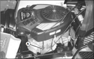
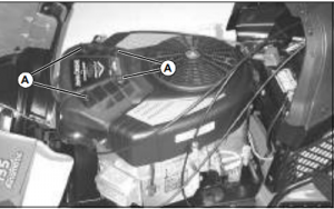
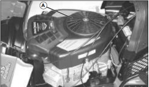
2. Remove fan belts, fan, and alternator (seeGroup 30). 
 
3. Remove turbocharger (if equipped) and exhaust manifold (see Group 35). 
 
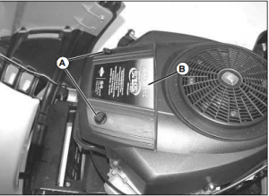
4. Remove rocker arm cover with vent tube. On engines having an Option Code label on rocker arm cover, be careful not to damage label (see Group 05). 
 
5. Remove water manifold with thermostats (see Group 30). 

6. Remove oil cooler piping and water pump (seeGroups 25 and 30).(Continued on next page) 
 
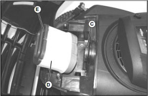
7. Remove dipstick, oil filter, and engine oil cooler.
Discard standard-flow oil cooler if oil contained metal
particles (see Group 25). 
 
8. Remove oil pressure regulating valve assembly(see Group 25).
 
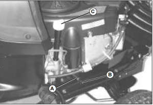
9. Remove fuel filter, fuel transfer pump, and fuel lines (see Group 40). 
 
10. Remove injection lines, injection pump, andinjection nozzles (see Group 40). 
 
11. Remove starting motor. 
 
12. Remove rocker arm assembly and push rods.Keep rods in sequence (see Group 05). Check forbent push rods and condition of wear pad contactsurfaces on rockers. 
 
13. Remove cylinder head. Check piston protrusion.Verify piston height selection (see Groups 05 and10).
14. Remove cam followers. Keep in same sequence as removed (see Group 20).
 
15. Remove oil pan (see Group 25). 
 
16. Remove flywheel and flywheel housing (see Group 15). 
 
17. Remove crankshaft pulley (see Group 15). 
 
18. Remove timing gear cover (see Group 20). 
 
19. Remove oil pump drive gear, outlet tube (and its O-ring in block) and pump body (see Group 25). 
 
20. Remove oil slinger, timing gears and camshaft.Perform wear checks (see  roup 20). 
 
21. Remove balancer shafts (4-cylinder only, if equipped), see Group 20. 
 
22. Remove engine front plate (see Group 20). 
 
23. Remove lube oil system by-pass valve (see  Group 25). 
 
24. Stamp cylinder number on rod (if required). Remove pistons and rods. Perform wear checks with  “PLASTIGAGE”. On 4 and 6-cylinder engines, remove  two at a time (see Group 10). 
 
25. Remove main bearings and crankshaft. Perform  wear checks with  PLASTIGAGE” (see Group 15). 
 
26. Remove cylinder liners and mark each one with  cylinder number from which removed (see Group 10). 
 
27. Remove piston cooling orifices (see Groups 10  and 15). 
 
28. Remove balancer shaft and camshaft bushings (if  equipped), see Group 20.
29. Remove cylinder block plugs and serial number plate (as required) when block is to be put in a “hot  tank” (see Group 10).   

30. Clean out liner bores (upper and lower areas)  with nylon brush (see Group 10).
 
31. Measure cylinder block (see Groups 10, 15, and  20)

 02.2024 John Deere Parts ADVISOR EPC(CF& AG& CCE)

This Article Introduces the Structure of the Deutz BFM1013 Diesel Engine

  (1) Introduction to the BFM1013 diesel engine. The Deutz BFM1013 diesel engine is an inline engine with two types: four-cylinder and six-c...