Translate

显示标签为“Deutz”的博文。显示所有博文

2025年8月27日星期三

This article introduces the maintenance of the DEUTZ FL413F/513 diesel engine body.


The body group is the support of the diesel engine and the installation base for the crankshaft connecting rod mechanism, valve mechanism and other major components of the diesel engine mechanism and system. The diesel engine body group mainly consists of the cylinder block (or engine block, crankcase), cylinder gasket, cylinder head, cylinder liner and oil pan.

2024 Deutz SerDia 4.0 SerDia2010 14.1.9.3 Highest Level 6 Diagnostic Software

(1) Structure of the body The FL413F/513 diesel engine body adopts a gantry structure (as shown in Figure 2-2). This structure has a relatively high body rigidity. The upper part of the V-shaped body is two cylinder liner mounting planes at a 90° angle to each other. The injection pump bracket and fan transmission box are installed in the middle, and the lower part is the oil pan joint surface. The cylinder liner mounting plane is at a 45° angle to the oil pan joint surface. The body is cast from gray alloy cast iron. The hardness is 180~250HB. The center distance between the cylinder liner mounting holes on the cylinder liner mounting plane is 165mm, and the hole diameter is 139mm. Due to the parallel connecting rod mechanism, the left and right cylinder liner mounting holes are not on the same center line and are offset by 29mm.

① The diameter of the bottom hole of the crankcase main bearing is φ 101 (+0.022)mm, and the third cross partition is dedicated to thrust positioning. The main bearing cover is tightened by two M16×1.5mm vertical bolts and two M10mm horizontal bolts at the same time. The main bearing cover is made of QT50-5 ductile iron.

Deutz Diagnostic Tool Communicator for Deutz Engine DECOM Controllers

② A φ22.5mm main oil channel bottom hole is cast in the crankcase, and a φ22mm oil pipe is installed; the main oil channel is connected to the main bearing bottom hole


(2) Characteristics of the engine body The FL413F/513 diesel engine body has the following characteristics.

① High degree of universalization, serialization and standardization. Except for the length, the other structural elements of the models with different cylinder numbers are basically the same.

② Compact structure and small size. The horizontal width of the oil pan joint surface is only 265mm, which is convenient for installation on the equipment.

③ The transmission gearbox and the crankcase are cast as one piece, which increases the overall rigidity of the rear part of the crankcase and the crankcase.

④ In addition to two vertical bolts, the main bearing cover and the engine body are fastened with two horizontal bolts. This better ensures the rigidity of the engine body and helps reduce the noise of the diesel engine.

(3) Main damage modes of the cylinder block The main damage modes of the diesel engine body are:

① Broken connecting rod bolts;

② Deformation, loss of roundness or deterioration of the coaxiality of the main bearing bottom hole due to the burning of the bearing;

③ Deformation or cracking of the cross-partition of the main bearing bottom hole due to overload operation or other factors;

④ Abnormal damage caused by other reasons, etc.

(4) Inspection points of the engine body (crankcase or cylinder block) The engine body of a diesel engine is the basic component of the diesel engine, and all moving parts are installed on it. Therefore, the quality of the engine body directly affects the running stability and reliability of the entire diesel engine. When overhauling a diesel engine, the quality of the engine body should be carefully checked, with a focus on the following parts.

① The quality of the bottom hole of the main bearing of the engine body, that is, check whether the main shaft hole is out of round, whether there are cracks or bearing rotation, and whether the coaxiality of all holes is out of tolerance.

② Whether the engine body water jacket, cross partition, etc. have quality problems such as cracks or looseness.

③ Whether the various installation surfaces (mainly the installation surfaces with the cylinder liner and cylinder head) are deformed or have pits, corrosion spots, etc.

④ Whether the relevant oil channels (such as: the main oil channel of the engine oil or the diesel oil channel of the single pump diesel engine, etc.) are intact. Only when the engine body is checked to confirm that there are no quality problems can it be used again. Otherwise, it should be repaired before use.

(5) Repair method of cracks in the engine block cross-plate When a diesel engine fails due to lack of oil, such as burning bearings or shaft seizure, the bottom hole of the main bearing bearing may be worn out and out of round, deformed or cracked. In this case, the bottom hole of the main bearing needs to be repaired. The repair points are shown in Table 2-1.

Deutz Serpic 2012 EPC Download & Installation Service Finial Version

If the technology is good enough, the best repair method is to use thermal spraying to repair the engine block (cylinder block) because it can completely restore the original standard size and accuracy requirements of the bottom hole of the main bearing of the engine block. A successful case in this regard is the use of thermal spraying to repair the engine blocks of several F12L513 diesel engines. After years of use, no quality problems have occurred in the repaired parts.

Insufficient degree makes the diesel engine unable to work normally. Similar faults have occurred many times. Especially when troubleshooting "cylinder pulling" and other faults on site, more attention should be paid.


2025年8月25日星期一

This article introduces the Deutz BFM1013 electronically controlled single pump diesel engine, its use and maintenance requirements Diesel engine operation points


(1) Preparation before starting To ensure safe driving, the following inspections should be carried out before starting.

2024 Deutz SerDia 4.0 SerDia2010 14.1.9.3 Highest Level 6 Diagnostic Software

① Check whether all parts of the diesel engine are normal, whether all accessories are connected reliably, and eliminate any abnormal phenomena.

② Check whether the electric starting system circuit wiring is normal and whether the battery power is sufficient.

③ Check the oil level in the oil pan and the injection pump assembly. The oil level should not be lower than the center line of the upper and lower limit marks of the oil dipstick.

④ Check the oil level in the fuel tank.

⑤ Open the fuel tank switch to allow diesel to flow to the fuel pump.

⑥ Use the fuel pump to remove air from the fuel system.

⑦ Check the cooling system and add enough water.

⑧ For diesel engines with power booster pumps, check whether the booster pump has sufficient circulating oil. It must not run idle. The oil suction vacuum at the booster pump inlet must not be higher than 0.02MPa, and the oil suction pipeline is not allowed to leak.

⑨ For new engines or diesel engines that have been parked for more than 5 days, the crankshaft should be rotated 3 to 5 times before starting.

⑩ For diesel engines that are parked for emergency use, in order to facilitate rapid start-up and operation in case of emergency, they should be started and tested every 3 to 5 days during the parking period until the water and oil temperatures reach above 60°C.

Deutz Diagnostic Tool Communicator for Deutz Engine DECOM Controllers

(2) Starting the diesel engine

After the preparatory work before starting is completed and confirmed to meet the requirements, it can be started. The clutch should be disengaged during starting. The starting steps are as follows.

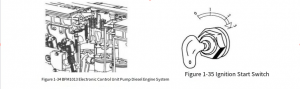
① Turn the ignition switch (see Figure 1-35) to start the diesel engine.

Note: The connection time should not exceed 5 seconds each time to protect the starter battery; after each start failure, it should be stopped for 60 seconds before starting again. If it fails three times in a row, the cause should be identified and the fault should be eliminated before starting again. Once the diesel engine is started, the lock switch should be turned back to its original position immediately.

For supercharged and supercharged intercooled diesel engines, since a supercharger is used, the engine should be idled for 3 to 5 minutes after each start to allow the oil pump to work properly and to build up the necessary oil pressure, ensuring that the pressure reaches the supercharger bearing at the top of the diesel engine.

② After the diesel engine is started, the oil pressure should be checked immediately by the oil pressure warning light and oil pressure gauge on the instrument panel. If there is any abnormality, the cause must be identified and the fault must be eliminated.

③ After the diesel engine is started, it should be idled for 3 to 5 minutes. It is strictly forbidden to accelerate or throttle immediately after starting.

④ When starting in winter, the air preheating button can be pressed, but it should not exceed 40 seconds.

(3) Cold start of diesel engine

① Introduction to the function of low-temperature starting device The currently produced "low-temperature start type" series diesel engines mainly use the intake air preheating method to improve the low-temperature starting performance of diesel engines. The CA6DE3 (BF6M1013) series engines use two intake air preheating methods: one is to ignite diesel to heat the cold air entering the engine intake manifold (flame preheater heating); the other is to use electrical heating (PTC air heater heating). The usage of both heaters is briefly described below.

a. Flame preheater. This device heats the intake air by igniting diesel injected into the intake manifold. This device automatically activates when the engine's coolant temperature falls below 0°C. When starting the diesel engine, the operator first places the ignition key (YI=Y) in the preheat position. After approximately 26 seconds, the preheat indicator light turns off, and the operator can start the engine.

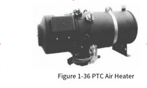
b. PTC air heater. The PTC air heater (shown in Figure 1-36) stores heat generated by electrical energy in the heater. During startup, hot air enters the cylinders first, ensuring a smooth engine start. When the driver wants to start the diesel engine, he or she should first press the preheat switch. After 6 minutes, the buzzer will sound, indicating that the preheater is finished. The driver can then reset the preheat switch and start the engine.

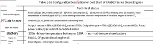
② Cold Start Components: The CA6DE3 series has a specially developed air heater. To ensure low-temperature starting performance, the vehicle's engine oil, diesel, battery, and other spare parts must be configured according to relevant requirements. Specific requirements are shown in Table 1-16.

③ Precautions

a. The flame preheater's glow plug is a consumable part with a normal lifespan of 400-500 cycles, or approximately two years. Therefore, the glow plug's operating condition should be regularly checked. If the glow plug is operating normally during starting, the temperature of its exposed portion should be significantly higher than that of surrounding components (by feel). If any abnormality occurs, the heat pipe resistor may be blown, and the glow plug should be replaced.

Deutz Serpic 2012 EPC Download & Installation Service Finial Version

b. After each start, ensure that the battery is fully charged to ensure a smooth start. c. When starting the diesel engine at low temperature after a long period of inactivity (more than 24 hours), the oil pump should be manually pumped several times before starting. At the same time, the residual air in the diesel filter should be released to keep the oil circuit clear for smooth starting.

(4) Operation of the diesel engine

① After starting the diesel engine, it should not be operated at full load immediately. Instead, the diesel engine should be heated by running it at low and medium speeds.

② During operation, the oil pressure and cooling water temperature should be constantly monitored. Full load operation is permitted only when the water temperature reaches above 60°C and the oil temperature reaches above 65°C. During normal operation, the oil pressure should be between 0.2 and 0.5 MPa, and the cooling water outlet temperature should be controlled within 95°C.

③ Always listen to the diesel engine for any abnormal noises. If any are detected, the engine should be stopped and checked immediately. After the cause is identified, it can be restarted and operated.

④ Always pay attention to the sealing condition of the oil and water connections; if there is any leakage, it should be handled immediately to prevent waste and environmental pollution, and oil or water should be replenished in time.

⑤ New or overhauled diesel engines need to run for 2000km at medium and low speeds and light loads before they are allowed to be used at full load.

⑥ The injection pump has been adjusted and the limit screws have been sealed before the diesel engine leaves the factory. Users are not allowed to remove the seals and adjust them at will during use. During operation, it is strictly forbidden to accelerate - shut down - coast - shift gears and then use the clutch to start the diesel engine.

(5) Shutdown of diesel engine

① When the diesel engine is stopped, the load and speed must be gradually reduced to idle speed, and it must idle for 5 minutes before stopping. It is strictly forbidden to stop at high speed unless it is an emergency to prevent the high temperature of the turbine from being transmitted to the floating bearing and the compressor seal ring, causing a supercharger failure. At the same time, it should be noted that the idling time should not be too long (generally not more than 20 minutes), as it is easy to cause oil leakage.

② When the temperature is below 5℃, if antifreeze is not used, the cooling water should be drained immediately to prevent the parts from freezing and cracking.

③ After each shutdown, any faults found during operation must be promptly eliminated and necessary inspections carried out.

④ If the diesel engine is not used for a long time, it must be cleaned and oil sealed as necessary to prevent rust.

(6) Diesel engine running-in A new or overhauled diesel engine must be run-in before it is allowed to run at full speed and full load. The running-in mileage on the vehicle is 2500km. Among them: 0~200km, empty vehicle running, speed not exceeding 40km/h; 200~1500km, load not exceeding 3t, speed not exceeding 60km/h; 1500~2500km, load not exceeding 3t. During the run-in period, the engine oil should be changed three times, at 500 km, 1000 km, and 2500 km, respectively. The air filter element and dust collector should also be cleaned.

At the end of the run-in period, the following maintenance should be performed:

① Clean the diesel engine oil pan, change the lubricating oil, and clean the oil pan oil filter;

② Tighten the oil pump drive gear nut;

③ Check the torque of the main bearing cap bolts;

④ Check the torque of the connecting rod bolts and the cylinder head bolts;

⑤ Check and adjust the valve clearance;

⑥ Replace the oil filter and remove dust from the air filter element;

⑦ Check the fuel injection advance angle; tighten the injection pump coupling bolts;

⑧ Remove the injection pump speed limiter screw, check the belt tension, and adjust it appropriately;

⑨ Tighten the screws connecting the supercharger to the exhaust manifold;

⑩ Check the suspension cushions for cracks and loose nuts.

2025年8月13日星期三

This article introduces the comprehensive use requirements of the Deutz BFM1015 diesel engine.


(1) Preparations before starting the diesel engine For the BFM1015 diesel engine, the following points should be noted when the new engine is put into use for the first time. ① Fill the diesel engine with qualified engine oil Before using the diesel engine, fill it with qualified engine oil that meets the use requirements of the diesel engine (the quality grade and viscosity requirements of the engine oil can be referred to the instruction manual of the diesel engine. If there is no reference material, it is recommended to use heavy-duty diesel engine oil of CF grade or above. The viscosity requirement is determined according to the ambient temperature. If it is used in the southern region for a long time, it is recommended to use 15W/40). The reference amount of engine oil is shown in Table 1-9.

Deutz Diagnostic Tool Communicator for Deutz Engine DECOM Controllers

② Filling the Oil Bath Air Filter with Engine Oil

Figure 1-31 Coolant Filling and Cooling System Venting

If this diesel engine is equipped with an oil bath air filter,

Before use, fill the air filter oil bowl 1 (see Figure 1-30) with engine oil of the same grade as the diesel engine to the line marked with the arrow.

b. Filling and Venting the Cooling System. Connect the water tank to the diesel engine's water inlet pipe 1 and water outlet pipe 2, as shown in Figure 1-31. Then, fill with coolant. Start the diesel engine and run it to normal operating temperature, i.e., the thermostat opens (pipe 2 becomes hot). At this point, check the fluid level in the cooling system and top up if necessary. c. Cooling System Protective Fluid. If conditions permit, add cooling system protective fluid to the cooling system. Cooling system protective fluid provides effective protection against rust, cavitation, and freezing, significantly extending the service life of the diesel engine's cooling system. The concentration of protective fluid in the coolant should not fall below or exceed the limits specified in Table 1-11. Table 1-11 Concentration requirements for cooling system protective fluid

d. Coolant preparation requirements. Coolant preparation requirements and their corresponding ambient temperatures are shown in Table 1-12.

2024 Deutz SerDia 4.0 SerDia2010 14.1.9.3 Highest Level 6 Diagnostic Software

(2) Starting, operating and stopping the diesel engine ① Diesel engine starting preparation Before starting, in addition to correctly adding engine oil, diesel and coolant, checking the connection status of each connection part and checking the customer instructions, the following preparations should also be carried out.

a. Check the battery and battery connection cable.

b. When starting with a flame preheating plug, no other auxiliary starting method (such as starting fluid) is allowed.

c. Never start the diesel engine with the governor removed.

② Starter use requirements The starter power-on time should not exceed 20 seconds at a time. If the diesel engine cannot start, wait 1 minute and try again. If the diesel engine fails to start successfully after two attempts, it is necessary to check the cause; start again after the cause is identified and the fault is eliminated.

③ Diesel Engine Starting Procedure a. Disengage the clutch to disconnect the drive equipment from the diesel engine. b. Use the hand lever or foot pedal to move the throttle handle to the medium speed position. c. Insert the key (as shown in Figure 1-32) and turn the key clockwise to position

1. The charge indicator and oil pressure indicator will illuminate. Continue turning the key clockwise to position

2. The starter motor will start. d. Immediately after the diesel engine ignites, release the key. The oil pressure and charge indicators will go out (normal temperature start). e. Cold Start: When the temperature is below 0°C, use a glow plug for preheating. Starting aids are not required at lower temperatures, making starting easier. The cold start glow plug operation procedure is as follows: Insert the key and turn it clockwise to position 1. Indicators 1, 2, and 3 will illuminate, and the diesel engine will preheat. Wait until preheat indicator 3 flashes (maximum 30 seconds). The diesel engine is now ready to start. Continue turning the key clockwise to position 2 to start the diesel engine. Once the diesel engine starts running, immediately release the key. The indicator light will go out. Slowly decelerate the engine and allow it to operate at a moderate load. Once the engine oil temperature rises, resume high-load operation.

④ Precautions for Normal Diesel Engine Operation: During diesel engine operation, monitor the oil pressure. After the engine is started, the oil pressure should be greater than 0.1 MPa and no less than 0.3 MPa at the rated speed. At this time, the charging indicator and oil pressure indicator should go out, and the coolant temperature gauge needle should be in the green zone. If any abnormality is detected, stop the engine and inspect it. During operation, avoid sudden accelerator pedaling, sudden acceleration and deceleration, or sudden stops from full load. Also, avoid operating the engine at low temperatures (referring to the diesel engine temperature) for extended periods, such as prolonged idling, as this can cause premature wear. Diesel engines consume some oil during normal operation and require timely oil addition. However, simply adding oil without regular oil changes is prohibited. During operation, always pay attention to whether the oil pressure and coolant temperature are normal. After work, if the engine is stored outdoors for a long time, pay attention to prevent rainwater from entering the fuel tank, exhaust pipe, intake pipe, etc. to avoid malfunctions. Tips: Ensuring that the air filter, oil filter and diesel filter are working reliably, adding oil and coolant that meet the requirements, and using the correct brand of diesel are the keys to ensuring the reliable operation of the diesel engine. ⑤ Diesel engine shutdown requirements The diesel engine must not be suddenly stopped from full load conditions. After unloading, it should be idle for a short time to stabilize the temperature before stopping. At this time, the charging indicator light and oil pressure indicator light will light up again. Turn the start key counterclockwise and pull it out. The charging indicator light and oil pressure indicator light should go out. (3) Diesel engine running-in requirements New diesel engines and diesel engines that have been overhauled must be run-in before being put into normal use. Practice has shown that the service life, reliability and economy of the diesel engine depend to a large extent on whether the diesel engine has been run-in correctly according to regulations in the early stage of use. The BFM1015 series diesel engine has a break-in period of 200 to 300 hours (depending on usage). Specific requirements are as follows: ① With the throttle at 2/3, operate at 1/4 load for 5 hours, 1/2 load for 5 hours, and 3/4 load for 5 hours. ② With the throttle at full throttle, operate at 1/4 load for 5 hours, 1/2 load for 5 hours, and 3/4 load for 25 hours. Repeat the break-in cycle several times until the predetermined break-in period is reached. ③ A run-in diesel engine can extend its service life and reduce fuel and oil consumption. However, idling or no-load operation is prohibited during the break-in period, as this will not achieve the desired break-in effect. ④ After the 50-hour run-in period, remember to perform an inspection. The main tasks include: draining the engine oil (the engine should be shut down and the oil temperature should be around 80°C), cleaning the oil pan before adding new oil, cleaning or replacing the oil filter or element, checking valve clearance, and inspecting and tightening all major connections, such as the air filter connection pipe, water pipe, and oil pipe. Important Note: Always perform a run-in according to specifications. This will extend the service life of the diesel engine and reduce diesel and oil consumption. During the run-in period, check the oil level twice daily; after the run-in period, check the oil level once daily.

Deutz Serpic 2012 EPC Download & Installation Service Finial Version

2025年8月12日星期二

This article introduces the maintenance of the Deutz FL413F/513 diesel engine body.


www.heavydutydiag.com

The body group is the support of the diesel engine and the installation base for the crankshaft connecting rod mechanism, valve mechanism and other major components of the diesel engine mechanism and system. The diesel engine body group mainly consists of the cylinder block (or engine block, crankcase), cylinder gasket, cylinder head, cylinder liner and oil pan

Deutz Diagnostic Tool Communicator for Deutz Engine DECOM Controllers

(1) Structure of the engine body The engine body of the FL413F/513 diesel engine adopts a gantry structure (as shown in Figure 2-2). This structure has a relatively high engine body rigidity. The upper part of the V-shaped engine body is two cylinder liner mounting planes at a 90° angle to each other. The injection pump bracket and fan transmission box are installed in the middle, and the lower part is the oil pan joint surface.

The cylinder liner mounting plane is at a 45° angle to the oil pan joint surface. The engine body is cast from gray alloy cast iron. The hardness is 180~250HB. The center-to-center distance between the cylinder liner mounting holes on the cylinder liner mounting plane is 165mm, and the hole diameter is 139mm.

Due to the parallel connecting rod mechanism, the left and right cylinder liner mounting holes are not aligned, but offset by 29mm. ① The crankcase main bearing bottom hole has a diameter of φ101 (+0.022)mm. The third cross-plate is used exclusively for thrust positioning.

Figure 2-2 F8L413F diesel engine block The main bearing cap is secured simultaneously with two M16×1.5mm vertical bolts and two M10mm horizontal bolts. The main bearing cap is made of QT50-5 ductile iron. ② A φ22.5mm main oil gallery bottom hole is cast in the crankcase, and a φ22mm oil pipe is installed; the main oil gallery communicates with the main bearing bottom hole.

(2) Engine body features The FL413F/513 diesel engine body has the following features. ① High degree of universality, serialization, and standardization. Models with different cylinder numbers have basically the same structural elements except for the length. ② Compact structure and small external dimensions. The horizontal width of the oil pan joint surface is only 265mm, which is convenient for installation on the equipment. ③ The transmission gearbox and crankcase are cast as one piece, which increases the overall rigidity of the rear part of the crankcase and the crankcase. ④ In addition to two vertical bolts, the main bearing cover and the engine body are fastened with two horizontal bolts. This better ensures the rigidity of the engine body and is also conducive to reducing the noise of the diesel engine. (3) Main damage modes of the cylinder block The main damage modes of the diesel engine block are: ① Due to the breaking of the connecting rod bolt; ② Due to the burning of the bearing, the bottom hole of the main bearing is deformed, out of round or the coaxiality is deteriorated; ③ Due to overload operation or other factors, the cross-partition of the bottom hole of the main bearing is deformed or cracked; ④ Abnormal damage caused by other reasons

2024 Deutz SerDia 4.0 SerDia2010 14.1.9.3 Highest Level 6 Diagnostic Software

.

(4) Inspection points of the engine block (crankcase or cylinder block) The engine block of the diesel engine is the basic component of the diesel engine, and all moving parts are installed on it. Therefore, the quality of the engine block directly affects the running stability and reliability of the entire diesel engine. When overhauling the diesel engine, the quality of the engine block should be carefully checked, focusing on the following parts. ① The quality of the bottom hole of the main bearing of the engine block, that is, check whether the main shaft hole is out of round, whether there are cracks or bearing rotation, and whether the coaxiality of all holes is out of tolerance. ② Whether there are cracks or looseness in the engine block water jacket, cross-partition, etc. ③ Check whether the mounting surfaces (mainly the mounting surfaces with the cylinder liner and cylinder head) are deformed or have pits, corrosion spots, etc. ④ Check whether the relevant oil channels (such as the main oil channel or the diesel oil channel of the single pump diesel engine) are intact. The engine body can only be used after it is checked to confirm that there are no quality problems. Otherwise, it should be repaired before use.

(5) Repair method of engine body cross partition crack When the diesel engine is short of oil and causes failures such as bearing burning and shaft seizure, it may cause the bottom hole of the main bearing of the engine body to wear and become out of round, deformed or cracked. At this time, the bottom hole of the main bearing of the engine body needs to be repaired. The repair points are shown in Table 2-1.


If the technology is good enough, the best repair method should be to use the thermal spray method to repair the engine body (cylinder block) because it can completely restore the original standard size and precision requirements of the bottom hole of the main bearing of the engine body. A successful case in this regard is the use of thermal spraying to repair the engine body of several F12L513 diesel engines. After years of use, no quality problems have occurred in the repaired parts.

Deutz Serpic 2012 EPC Download & Installation Service Finial Version

As shown in Figure 2-3, if a crack appears in the cross-plate of a diesel engine (cylinder block) at the location shown (left image in Figure 2-3), it can be repaired using the following methods: ① Use a grinding wheel or other cutting device to create a triangular groove at the crack (the size can be adjusted according to the actual crack condition).

② Heat the cross-plate to a certain temperature (the specific temperature depends on the engine block material) and maintain it at this temperature for a certain period of time.

③ Use the same hardfacing (or thermal spray) material as the engine block for hardfacing or spraying, ensuring that the entire main bearing bottom hole is welded or sprayed.

④ After the engine block has completely cooled to room temperature, perform precise boring on a jig boring machine, ensuring that the dimensions and coaxiality of all bottom holes meet the engine's technical requirements.

Regardless of the method used to repair a damaged engine block, the key is to know the standard dimensions and tolerances of the cylinder block main bearing bottom holes. These can be determined through pre-measurement and analogy. The standard dimensions of the bottom hole of the main bearing of some Deutz air-cooled diesel engines are shown in Table 2-2.

Special note: When using the thermal spray method to repair the bottom hole of the main bearing of the diesel engine cylinder block, before precision machining the hole diameter, the main bearing cover bolts must be tightened according to the main shaft bearing cover bolt tightening torque requirements. If the bolts are not tightened properly, the precision machined bottom hole will be deformed, causing the crankshaft to rotate with difficulty or even unable to rotate. This requires special attention.

(6) Cleaning requirements for the bottom hole of the cylinder head bolt After the FL413F/513 diesel engine is disassembled for overhaul or on-site troubleshooting, a large amount of dust or debris will fall into the bolt bottom hole (as shown in Figure 2-4). If it is not cleaned up, it will seriously affect the tightening of the cylinder head bolts. Therefore, when performing on-site maintenance work such as disassembling the cylinder head, special attention should be paid to the cleaning of the cylinder head bolt bottom hole. ① Before removing the cylinder head bolts, clean as much dust and debris as possible from the area around the bolts to prevent them from falling into the bolt base holes. If dust or debris falls into the bolt base holes, it may cause the cylinder head to not be tightened to the required degree (the required tightening torque has been met, but the cylinder head is not actually tightened). ② If debris or dust accidentally falls into the bolt base holes while removing the cylinder head bolts, be sure to remove all of it. Never install and tighten the bolts without cleaning the bolt base holes. ③ The basic method for removing dust and debris from the bolt base holes is as follows:

a. Pour a certain amount of kerosene (or diesel) into the bolt base holes, let them soak for a certain period of time, then use high-pressure air to blow out the dust and debris.

air to blow out the dust and debris. b. If high-pressure air cannot blow the bolt holes clean, use the following method to completely remove accumulated dust and debris: Take a used cylinder head bolt, grind the bottom flat, and grind three vertical grooves approximately 5mm deep in the threaded area.

Manually screw the bolt in and out repeatedly until it is completely free of dust and debris.

Note: The above step (cleaning dust from the bolt holes) is extremely important. Failure to do so may result in insufficient tightening of the cylinder head bolts, causing the diesel engine to malfunction. Similar failures have occurred numerous times, and this is especially important when troubleshooting problems such as "cylinder scuffing" on-site.


2025年8月10日星期日

This article describes the installation requirements for the unit injection pumps on the Deutz BFM1013 diesel engine.


The unit injection pumps used on the BFM1013 diesel engine are critical components of the fuel supply system. Each unit pump is independent of the others and controlled by a single fuel supply rack. Each unit pump is installed in a corresponding mounting hole on the left side of the cylinder block, secured by two fixing bolts and driven by a corresponding cam on the camshaft, thus providing separate fuel injection.

Deutz Diagnostic Tool Communicator for Deutz Engine DECOM Controllers

Figure 1-27 Adjusting the Fuel Rack of a BFM1013 Diesel Engine 1—Fuel Rack Stroke (dashed line); 2—Stop Position; 3—Fuel Rack; Y = Rack Stroke; X = 0.3 to 1.3 mm

2024 Deutz SerDia 4.0 SerDia2010 14.1.9.3 Highest Level 6 Diagnostic Software

Figure 1-28 Installing the Unit Pump 1—Rack Positioning Tool; 2—Casing; 3—Fuel Rack Guide Sleeve; 4—Unit Pump Fastening Bolts

According to the installation instructions in Figure 1-28, the correct installation procedure is as follows. ① After the diesel engine is turned off, place the fuel injection pump speed control rack in the stop position. Use a bolt from a special tool to hold the rack in place from the end to prevent movement in the fuel supply direction, maintaining the single pump in its original assembly position. ② Install the unit pumps one by one. Turn the drive cam under the unit pump to its base circle position, then place the adjusted unit pump into the unit pump hole in the cylinder block. ③ Pre-tighten the unit pump's mounting bolts with a torque of 5 N·m. Then, loosen them approximately 60° in the opposite direction. Use a torque wrench to try to rotate the unit pump, accurately reading and recording the torque M. ④ Use a wrench to slowly rotate the unit pump counterclockwise until it stops. ⑤ Turn the unit pump counterclockwise until the torque reaches (M+1) N·m, then cross-tighten the unit pump's mounting bolts. ⑥ Tighten the unit pump's mounting bolts alternately in three steps, with tightening torques of 7 N·m, 10 N·m, and 30 N·m. ⑦ After assembly is complete, loosen the bolts on the special tool and remove the tool to restore the original assembly.

Deutz Serpic 2012 EPC Download & Installation Service Finial Version

2025年8月4日星期一

This Article Introduces the Use and Maintenance of Deutz low-pressure oil Circuit System


2024 Deutz SerDia 4.0 SerDia2010 14.1.9.3 Highest Level 6 Diagnostic Software

Figure 1-22 Composition of the BFM1013 diesel engine single pump fuel system 1-Fuel tank; 2-Fuel inlet pipe; 3-Fuel pump; 4-Diesel pipe; 5-Diesel filter; 6-Fuel inlet pipe; 7-Single pump; 8-High-pressure oil pipe; 9-Injector; 10-Injector return pipe; 11-Return oil overflow valve; 12-Return oil pipe; 13-Distance between the inlet and outlet pipes of the fuel tank

(1) Composition of the single pump diesel engine fuel system ① Function Like the ordinary fuel system, the function of the single pump fuel system is to deliver a certain amount of fuel to the combustion chamber of the diesel engine at a certain pressure. ② Composition of the low-pressure oil circuit As shown in Figure 1-22, the single pump fuel system consists of a diesel tank, a low-pressure oil pump, a fuel filter (coarse filter, fine filter), and corresponding oil and other components. Diesel fuel flows from the fuel tank 1, passes through the fuel transfer pump 3, and enters the diesel filter 5. After filtration, it enters the low-pressure oil chamber cast in the cylinder block in non-electronically controlled models. The return fuel also flows into this chamber. The pressure in the low-pressure oil chamber is 0.5 MPa. If the diesel engine experiences insufficient power, the pressure in the low-pressure oil circuit should be measured first. The measurement location is at the external connection of the low-pressure oil circuit. At a diesel engine speed of 2300 rpm, p ≥ 0.45 MPa. ③ High-pressure Oil Circuit: The fuel in the low-pressure oil circuit flows from the unit pump through a short high-pressure oil pipe to the injector. When the pressure reaches 25.0 MPa, the injector opens, spraying the fuel into the combustion chamber in a mist form, where it mixes with air to form a combustible mixture. The oil pressure in the oil circuit from the diesel tank to the low-pressure fuel chamber joint is established by the fuel transfer pump. The oil pressure of the fuel transfer pump at the rated speed of the diesel engine is generally about 0.5MPa. Therefore, this section of the oil circuit is called the low-pressure oil circuit and is only used to supply oil to the single pump. The oil pressure in the oil circuit from the single pump to the injector is established by the single pump and is about 160MPa. ④ Fuel return Since the fuel supply of the fuel transfer pump is more than 10 times greater than the oil output of the single pump, a large amount of excess fuel flows back to the diesel tank through the pressure limiting valve 11 and the return pipe 12 (see Figure 1-22). The large amount of return fuel is used to carry away the air in the oil circuit, which has an automatic exhaust function. (2) Use and maintenance of the low-pressure oil circuit system The BFM1013 mechanical single pump diesel engine has two low-pressure oil circuit pressure systems: 0.3MPa and 0.5MPa. ① Low-pressure Oil Line Pressure Testing: Stable pressure in the low-pressure oil line is crucial to the diesel engine's power output. If the diesel engine experiences underpower, first check (measure) the pressure in the low-pressure oil line, controlled by the pressure-limiting valve 11 (see Figure 1-22). The primary cause of injector leakage is insufficient low-pressure oil line pressure, leading to cavitation of the injector components. Therefore, ensure the low-pressure oil line pressure and replace or clean the diesel filter promptly. The low-pressure oil line pressure measurement location is shown in Figure 1-23.

Deutz Diagnostic Tool Communicator for Deutz Engine DECOM Controllers

Figure 1-23: Low-pressure Oil Line Pressure Measurement Low-pressure oil line pressure limits: 0.3MPa system, p ≥ 0.20MPa (n = 2200 rpm); 0.5MPa system, p ≥ 0.45MPa (n = 2300 rpm). Because the single-pump system requires a high pre-pressure for the fuel, it is necessary to test the fuel system pressure. If the measured pressure is lower than the specified value, the fuel pump and return oil relief valve must be inspected. ② Fuel Pump Flow Check: The fuel pump (Figure 1-24) not only supplies fuel to the injection pump but also cools the fuel system. Therefore, the fuel pump's fuel flow rate is significantly greater than the injection pump's needs. For this reason, this engine uses a diaphragmless rotor-type fuel pump with a fuel flow rate of 12 L/min at a supply pressure of 0.5 MPa. To verify the fuel flow rate, at the return oil line (the oil line after the return oil relief valve), a minimum of 8 L/min of return oil should be observed at maximum idling speed. If the return oil flow rate is lower than this value, the fuel pump must be replaced. ③ Checking the Return Oil Relief Valve: The return oil relief valve (shown in Figure 1-25) establishes a minimum pressure in the low-pressure oil circuit to meet the instantaneous fuel delivery requirements of the injection pump. If the measured pressure is lower than the above value, the return oil relief valve should be replaced, provided that the fuel delivery pump is not faulty. Note: The low-pressure oil circuit pressure of the unit pump is higher, and conventional fuel supply system return oil check valves may not be able to meet the pressure buildup requirements. Therefore, a dedicated unit pump fuel system return oil relief valve must be used.

Deutz Serpic 2012 EPC Download & Installation Service Finial Version

2025年8月3日星期日

This Article Introduces the Use and Maintenance Requirements of the Deutz BFM1013 Diesel Engine.

 The BFM1013 diesel engine uses a single pump fuel system. For diesel engines using a single pump fuel supply system, the maintenance and repair of the single pump are completely different from those of traditional diesel engine injection systems, and have many special requirements, which brings a lot of trouble to users and repairers. Due to the special nature of the BFM1013 diesel engine injection system, most of its use and maintenance work revolves around the fuel system. If the maintenance work is not in place, the fuel system will often have problems and cause the diesel engine to malfunction. Therefore, it is very important to master the maintenance points of this diesel engine

Deutz Diagnostic Tool Communicator for Deutz Engine DECOM Controllers

(1) Method for draining the low-pressure oil circuit of the diesel engine The BFM1013 diesel engine fuel system uses a single pump fuel supply system, which has certain special features in removing air from the fuel system. Because unit injection pumps require high fuel pre-pressure, they have two systems: 0.3MPa and 0.5MPa (for a specific diesel engine, only one of these systems may be used). Normally, the pressure should be no less than 0.2MPa (0.3MPa system) and 0.45MPa (0.5MPa system). Therefore, for a 0.5MPa system, the return oil bolt's spring force is much greater than that of an in-line pump, making it difficult to bleed the fuel using a standard hand pump. Improper operation can make it difficult to remove air. Incomplete bleeds may cause difficulty or even failure to start the diesel engine, and may also cause cavitation in the unit pump and pump chamber. ① BFM1013 Diesel Engine Fuel System Bleeding Methods: If a diesel engine fails to start due to air in the fuel system, the following three methods are recommended. a. Before draining, loosen the high-pressure fuel line compression nuts on the injectors and use a hand pump to pressurize and vent fuel until bubble-free fuel flows from all high-pressure fuel lines. Then, tighten the high-pressure fuel line to complete draining. b. Before draining, tighten the high-pressure fuel line nuts on the unit pumps and use a hand pump (Figure 1-19) to pressurize and vent fuel until bubble-free fuel flows from all high-pressure fuel line outlets. Then, tighten the high-pressure fuel line nuts to complete draining. c. Before draining, first loosen the return oil relief valve on the low-pressure fuel chamber, rather than loosening the bleed bolt on the fuel filter as with in-line pumps. Then, pump oil to vent fuel until bubble-free fuel flows. After draining, tighten the return oil relief valve to complete draining. Note: Regularly loosening the high-pressure fuel line to vent fuel is not recommended. Of the above methods for draining, the first one is the most effective, but it's relatively tedious and complex. If you're not familiar with diesel engines, you need to be careful when using it to avoid damaging the valve cover gasket and causing oil leaks.

2024 Deutz SerDia 4.0 SerDia2010 14.1.9.3 Highest Level 6 Diagnostic Software

Figure 1-19 BFM1013 diesel engine hand oil pump

c. Before draining, loosen the return oil relief valve on the low-pressure oil chamber, rather than loosening the bleed bolt on the fuel fine filter as with an in-line pump. Then pump the oil to bleed air until bubble-free fuel flows out. After draining, tighten the return oil relief valve to complete the draining process. Note: Regularly loosening the high-pressure oil line to bleed air is not recommended. Of the above methods for draining, the first one is the most effective, but it's relatively tedious and complex. If you're not familiar with diesel engines, you need to be careful when using it to avoid damaging the valve cover gasket and causing oil leaks. Regardless of the method used to drain the diesel fine filter in the unit pump fuel system of some diesel engines, it is imperative that all air in the fuel system be completely expelled. Otherwise, starting the diesel engine will be difficult. ② Bleeding Methods for Other Unit Pump Diesel Engine Fuel Systems: Some units are equipped with a drain device (indicated by the arrow in Figure 1-20). The draining requirements are as follows.

Figure 1-20 Low-pressure fuel line drain device

Figure 1-21 Draining the oil-water separator water collector

a. Loosen the bleed plug at the top of the fuel filter and use the hand pump on the coarse filter to drain until the fuel filter is full of fuel and the fuel flowing out of the bleed plug is free of bubbles. Then tighten the bleed plug.

b. Loosen the bleed plug at the top of the unit pump chamber and use the hand pump to drain until the pump chamber is full of fuel and no bubbles are emitted. Then tighten the bleed plug.

c. Loosen the connectors connecting the high-pressure fuel lines to the injectors of each cylinder. Use a hand pump to expel air from the high-pressure fuel lines until fuel flows out. Then tighten the connectors.

d. After draining, wipe clean the fuel flowing out of the diesel engine and the frame before starting the diesel engine. e. It is forbidden to use the starter to drag the diesel engine for draining.

f. During the draining process, avoid splashing the fuel onto the exhaust pipe, starter, wiring harness (especially the connector). If it is accidentally splashed, wipe the fuel clean.

g. During the draining operation, the fuel must be kept clean and free from contamination.

(2) Precautions for the use of the single pump fuel supply system

① Since the single pump injection pressure is high, the quality requirements for the fuel are relatively strict. Therefore, the fuel system of the diesel engine should adopt at least a two-stage filtration system (coarse filtration and fine filtration). If conditions permit, a special oil-water separator filtration system can be installed. ② The fuel should be clean light diesel that meets national standards and must be precipitated and filtered for at least 2 to 3 days.

③ Regularly replace the diesel filter and clean the diesel tank.

④ Regularly drain the diesel coarse filter with oil-water separator, as shown in Figure 1-21.

⑤ During disassembly and maintenance, ensure the work area is clean to ensure a clean installation of the unit pump.

⑥ The unit pump high-pressure fuel line is a single-use component and should generally not be reused after disassembly.

⑦ It is strictly forbidden to disassemble the high-pressure fuel line while the diesel engine is running. Because the pressure within the high-pressure fuel line can reach 180.0 MPa and there is a pressure hold delay, the high-pressure fuel line should be disassembled 1 minute after the engine is shut down.

⑧ If the diesel engine experiences malfunctions such as difficulty starting, insufficient power, or prone to stalling, first inspect the low-pressure fuel line of the unit pump fuel system.

Deutz Serpic 2012 EPC Download & Installation Service Finial Version

2025年8月1日星期五

This article introduces the comprehensive use requirements of the DEUTZFL513 diesel engine.


(1) Basic requirements for the first use of diesel engine When a new diesel engine (i.e. new equipment) is put into operation for the first time, the following aspects should be noted. ① Regardless of the length of the original running time of the diesel engine, it is recommended to replace the engine oil and oil filter before it is put into formal use. This is because the brand of the test oil used by the equipment manufacturer may not be the same as the brand of the oil used by the user. To avoid mixing different brands of oil, the engine oil and oil filter (including bypass oil filter or centrifugal filter, etc.) should be replaced before the new equipment is put into use for the first time.

Deutz Diagnostic Tool Communicator for Deutz Engine DECOM Controllers

(2) Precautions for starting and stopping the diesel engine ① Preparation before starting. After cleaning the diesel tank and replacing the diesel filter, or when using a new diesel engine or a diesel engine after overhaul for the first time, the fuel system must be vented, otherwise, the diesel engine may not start.

fine filter and use a hand pump to pump diesel until bubble-free diesel flows out of the bleed hole. ② Precautions for starting a diesel engine are as follows: a. Disconnect the working device and ensure the engine starts without load. b. Position the throttle lever to 1/4 of full throttle. c. Start the engine. As soon as the engine ignites, release the start switch immediately. Note: During each start, the starter motor must not operate continuously for more than 10 seconds. If the engine fails to start three times in a row, wait at least 1 minute before starting again. d. After starting the engine, allow it to preheat for at least 3 minutes before operating at full load. During winter operation, the preheating time should be extended (at least 5 minutes). e. After starting, carefully monitor the engine oil pressure. ③ Precautions for shutting down a diesel engine. A diesel engine should not be shut down suddenly from full load. Under normal circumstances, it should be idled for 3-5 minutes after unloading, allowing the engine temperature to cool before shutting down. It is best to wait until the oil temperature is below 70°C and the cylinder head temperature is below 80°C before shutting down the engine. In special circumstances, the engine should also be shut down after unloading the engine whenever possible. If a diesel engine suddenly stops while in use (at full load), it is imperative to immediately rotate the crankshaft to prevent residual heat buildup in the engine's moving parts, which can cause problems such as "cylinder scuffing," "shaft seizure," and "burned bearings."

2024 Deutz SerDia 4.0 SerDia2010 14.1.9.3 Highest Level 6 Diagnostic Software


(3) Precautions for winter operation of diesel engines When using a diesel engine in winter, the following points must be noted.

① Winter engine oil must be used. Different brands of winter engine oil should be selected according to the ambient temperature. For details, please refer to the oil selection requirements or the relevant requirements of the instruction manual.

② Use winter fuel. When the ambient temperature is above 0 to 10°C, use 10# diesel. When the ambient temperature is -10 to -30°C, use -30# diesel. When the ambient temperature is below -30°C, use -50# diesel. If the incorrect diesel is used, for example, using 0# diesel at -5°C, wax precipitation from the diesel may clog the filter, causing the engine to malfunction. Therefore, it is essential to use diesel that is appropriate for the ambient temperature.

③ Drain (or clean) the sediment from the fuel tank at least monthly.

④ When the ambient temperature is below -20°C, regularly apply cold-resistant grease to the flywheel ring gear to ensure proper starting.

⑤ When starting a diesel engine in winter, pay special attention to the following points.

a. If the cold start limit temperature is too low, use a preheating device.

b. Ensure the battery is fully charged.

c. Use flame heating plugs. When the ambient temperature is below -25°C, you can use flame heating plugs to preheat and start the diesel engine. To do this: Place the start switch in the preheat position, preheat for 60 seconds, wait for the yellow indicator light to illuminate, and then preheat for another 20-30 seconds before starting the diesel engine. If the engine fails to start successfully once, preheat it for another 1-3 minutes before starting again. Each start should not exceed 10 seconds.

d. When the ambient temperature is below -25°C, the engine must be preheated entirely by other means before starting. For example, hot air generated by a combustion heating device can be used to circulate the engine's internal heat, or the oil in the oil pan can be preheated using a special heating device.

e. When used in winter, the engine should generally not be operated at low temperatures, low speeds (n ≤ 800 rpm), and no load for more than 30 minutes.

f. When starting the engine, avoid operating it at maximum idling speed.

Deutz Serpic 2012 EPC Download & Installation Service Finial Version


(4) Precautions for diesel engine operation in summer The weather is hot in summer, and the operating environment becomes relatively harsh for air-cooled diesel engines. In order to ensure the normal operation of air-cooled diesel engines in summer, special attention should be paid to the following points.
 
① The continuous working time of the diesel engine at full load should not exceed 60 minutes. If the operation limit requires continuous operation for a long time, it should be slowed down (n=800~900r/min) after at least 60 minutes and cooled for 3~5 minutes. This can avoid abnormal damage caused by overheating of the diesel engine.
 
② Select engine oil suitable for summer use according to the ambient temperature. Regularly check the oil quality. If the oil appears black or deteriorates, replace it immediately.
 
③ Regularly check the operation of the fan system and clean the fan hydraulic coupling regularly; ensure that the fan thermostat and electronic control device are always in good condition.
 
④ Regularly clean cooling surfaces such as the cylinder liner, cylinder head, and oil radiator to prevent excessive dust accumulation on the cooling surfaces, which may affect the engine's overall heat dissipation efficiency.
 
⑤ Do not shut down the engine immediately at full load. Run the engine at idle speed (800-900 rpm) for at least 3-5 minutes before shutting down. It is best to wait until the oil temperature is below 70°C and the cylinder head temperature is below 80°C before shutting down.
 
⑥ If the diesel engine suddenly stops at full load under special circumstances, measures must be taken to prevent "cylinder pulling" or "shaft seizure" failures.


Deutz FL513 series diesel engine Structure Introduction

FL513 series air-cooled diesel engine structure introduction Deutz FL513 series diesel engine (as shown in Figure 1-8) marks the beginning of a new era of air-cooled diesel engines. This series of diesel engines uses independent cylinder liners with heat sinks and a one-cylinder-one-head modular structure. The parts are highly versatile and have a wide range of uses.

Deutz Diagnostic Tool Communicator for Deutz Engine DECOM Controllers

With the gradual application of electronic technology, the environmental adaptability of diesel engines has gradually increased. Compared with the FL413F series diesel engines, the technical progress of the FL513 series diesel engines mainly includes the following aspects.

(1) Improvement of combustion chamber The FL513 series air-cooled diesel engines have undergone major changes in the structural shape of the combustion chamber (compared with the FL413F model). The combustion chamber of the non-supercharged model has been improved from an oblique cylindrical (U) combustion chamber to a W-shaped combustion chamber; although the supercharged models all have W-shaped combustion chambers, their structural dimensions have changed significantly, as shown in Figure 1-9.

Through the improvement of the combustion chamber, the diesel engine's combustion system has been improved and the combustion has been more complete, thus greatly improving the various performance indicators of the diesel engine.

2024 Deutz SerDia 4.0 SerDia2010 14.1.9.3 Highest Level 6 Diagnostic Software

(2) Improvement of the fuel supply system

①The A-type pump was changed to a P-type pump, which increased the pump oil pressure (the plunger diameter was increased).

②Injector nozzle improvement. The nozzle holes of the non-supercharged diesel engine were changed from 2 holes to 4 holes, and the injection pressure was increased.

③Reduced fuel consumption and improved torque characteristics, as shown in Figure 1-10.

(3) Improvement of output power

The FL513 model basically retains the basic structural features of the FL413F model: V-type 90° angle, also divided into inline 5, 6 cylinder, V-type 6, 8, 10, 12 cylinder supercharged and non-supercharged models. The turbocharged diesel engine has reduced its rated speed (from 2500r/min to 2300r/min) by improving the combustion mode and the injection pump system, while the non-turbocharged diesel engine has reduced its rated speed (from 2500r/min to 2300r/min) by increasing the cylinder diameter (from 125mm to 128mm), improving the fuel supply system (injection pump) and the combustion mode. The rated power has not only remained unchanged, but also widened the power output range of the diesel engine, thereby greatly improving the adaptability, reliability and service life of the diesel engine. In addition, the overall noise of the diesel engine has also been reduced. The power comparison curve of the BF8L513 and F8L413F diesel engines is shown in Figure 1-11. (4) Improvement of exhaust emission indicators After a series of improvement measures, the exhaust indicators of the FL513 model have been greatly reduced compared with the FL413F model, as shown in Figure 1-12. The emission indicators of the FL513 model have been greatly improved and can meet the requirements of the Euro II standard.

Deutz Serpic 2012 EPC Download & Installation Service Finial Version

(5) FL413F/513 diesel engine combustion process ① The "D" process of Deutz diesel engine combustion: The axis of the oblique cylindrical combustion chamber (as shown in Figure 1-13) intersects the cylinder centerline at an acute angle. Two oil jets of equal thickness and at an acute angle (28°) are sprayed into the vicinity of the oblique cylindrical combustion chamber wall. The oil jets are blown to the periphery by a strong rotating airflow with an intake tangential velocity of approximately 90 m/s (swirl ratio of approximately 2.6). The oil-air mixture at the center of the combustion chamber has an appropriate concentration and ignites first (the ignition delay period is approximately 2° to 3° crankshaft angle). The oil-air mixture at the combustion chamber wall has a higher concentration and, due to the low temperature, the chemical reaction is controlled and does not ignite immediately. Subsequently, due to the effect of thermal mixing, the combustion gases at the combustion chamber walls flow toward the center. Due to their lower temperature and higher density, the combustion gases at the center are flung toward the chamber walls by the centrifugal force of the swirling vortex, remixing with the denser fuel-air mixture at the chamber walls and further burning. The Deutz "D" combustion process is characterized by low combustion noise, avoidance of combustion shock during startup, reliable startup at ambient temperatures above -15°C, good fuel economy, and low thermal load. The Deutz "D" combustion process is used in the FL413F series non-turbocharged diesel engine. ②Deutz diesel engine combustion "Z" process. The Deutz "Z" process utilizes a W-shaped combustion chamber (as shown in Figure 1-14). Fuel is injected directly into the combustion chamber at high pressure through a four-hole injector. The fuel-air mixture is formed by the axial rotation of the air along the cylinder liner (swirl ratio 1.7 ± 0.2) and the "squeeze turbulence" inherent in the combustion chamber.


(6) FL513/413F Diesel Engine Main Technical Parameters The FL513/413F series air-cooled diesel engines have a wide variety of models, and only some models are included. Their main technical parameters are shown in Table 1-1.

(7) Structural features of FL513 series air-cooled diesel engines ① High degree of standardization, serialization and universalization. The commonality of all engine parts is very high, reaching more than 67% by type and about 85% by number. Whether it is a 6-cylinder engine, an 8-cylinder engine or a 12-cylinder engine, except for the crankcase, crankshaft, camshaft, oil pan, injection pump and intake and exhaust pipes, other parts are universal or basically universal. ② Simple structure and easy maintenance. The one-cylinder-one-head structure facilitates maintenance services such as cylinder pulling, replacement of pistons, cylinder liners and piston rings, and adjustment of valve clearance. ③ Long service life, good reliability and low failure rate. Due to the use of an air cooling system, the failure rate of the cooling system is greatly reduced. Compared with water-cooled diesel engines, the failure rate is reduced by about 34% (as shown in Figure 1-15). The service life can reach more than 10,000 hours. When used on railways or in construction machinery, this series of diesel engines operates at reduced power, with actual operating power at least 10% below rated power. This further extends the engine's service life and significantly reduces the likelihood of engine failure and damage. ④ Low noise and exhaust pollution. This series of diesel engines utilizes advanced combustion theories and noise reduction technologies, resulting in significantly lower noise levels than water-cooled diesel engines of the same power while also significantly reducing emissions. The low-pollution (FL513W) model of this series of diesel engines boasts very high emission standards, making it particularly suitable for use in underground mines and tunnels, and is highly sought after by users. ⑤ Excellent economic performance. This series of diesel engines boasts a fuel consumption rate of 225g/kW·h under rated conditions and a minimum fuel consumption rate of 216g/kW·h, representing oil consumption less than 1% of total fuel consumption. Furthermore, their reliable service life and low failure rate significantly reduce the engine's operating costs, further improving its overall economic performance. ⑥ Good power performance and strong adaptability. a. Strong environmental adaptability: Can be used normally in an ambient temperature of -40-50°C.

b. Wide power range (64 to 386 kW), meeting a variety of applications. This series of diesel engines is widely used in trucks, construction machinery, mining machinery, luxury coaches, railway maintenance equipment, and special vehicles. c. The output power of the FL513 series air-cooled diesel engine includes fan power consumption, and its output power is close to the net output power of the diesel engine, thus providing excellent power performance.


This article explains how to adjust the wear pads of the extended bucket of a JCB backhoe loader

  Preparing the Cab Frame Aperture 1  If damp or wet, dry the aperture area using a hot air gun (sourced locally). 2  Use 'Active Wipe 2...