Note: If the fault is intermittent and does not repeat, please refer to the "Intermittent Low Power or Power Cut-off" section. If the fault is continuous and recurring, continue with this procedure.
(1) Possible Causes.
1) Diagnostic Codes.
2) Electrical Connectors.
3) Cold Mode.
4) Throttle Signal.
5) Injection Drive Pressure.
6) Individual Injectors.
7) Fuel Supply.
8) Intake and Exhaust Systems.
(2) Recommended Actions. Note: If the fault only occurs under certain operating conditions (high idle, full load, and engine operating temperature, etc.), test the engine under these conditions. Diagnosing and troubleshooting the fault symptoms outside of these conditions can be misleading.
1) Diagnostic Codes. Check the Caterpillar Electronic Technology (Cat ET) for self-diagnostic codes. Before continuing this procedure, troubleshoot and resolve all self-diagnostic codes.
2) Electrical Connectors. Check that ECM connectors J1/P1 and J2/P2, as well as the unit injector connectors, are installed correctly.
Caterpillar ET 2026A & 2019C Electronic Technician Diagnostic Software Download and Installation
3) Cold Mode. Use Cat ET to verify that the engine has exited cold mode. Operating in cold mode can cause engine instability and limit engine power.
4) Throttle Signal. Monitor the throttle signal on Cat ET. Verify that the throttle signal is stable from low idle to high idle.
5) Injection Drive Pressure.
① Check the engine oil level. Engine oil supplies the injection drive pressure circuit. The engine oil level must be maintained at the correct level for fuel injection. Note: If oil has been drained from the unit injector hydraulic pump, the pump must be primed.
② If the engine has recently undergone maintenance, there may be air in the injection drive pressure circuit.
① Fully warm up the engine and operate it under load to purge air from the fuel injection drive pressure circuit.
② Compare the actual drive pressure on the CAT ET with the required drive pressure. If the two readings do not exceed 2000 kPa during the fault, the problem is not in the fuel injection drive pressure circuit.
③ Check the seal on the fuel injection drive pressure control valve. If the seal is faulty, replace it and repeat step
③.
④ Check the wiring harness connected to the fuel injection drive pressure control valve for open circuits and/or short circuits.
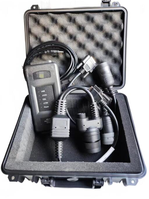
CAT Comm Adapter3 478-0235 Diagnostics for Caterpillar
⑤ Measure the coil resistance on the fuel injection drive pressure control valve. If the coil resistance exceeds (10 ± 5) Ω, replace the fuel injection drive pressure control valve. Note: Leaking liquid under pressure, even at the size of a pinhole, can penetrate human tissue, causing serious injury or even death. If liquid sprays into the skin, seek immediate treatment from a doctor familiar with this type of injury.
Always use a wooden board or cardboard when checking for leaks.
⑦ Perform a fuel injection drive pressure overload test using the ET. If the fuel injection drive pressure is low, there may be a leak in the high-pressure fuel supply circuit.
a. Remove the plug from the fuel injection drive pressure control valve and the unit injector connector.
b. Stop the unit injector operation using the ET and/or engine stop switch.
c. Remove the valve cover.
d. While checking for leaks at the drain port of the unit injector connector and the bridging cylinder block seal, crank the engine.
e. Repair any leaks and repeat step ③.
f. If the fuel injection drive pressure is still low during cranking, the pump compensator flow controller may be faulty. Replace the pump compensator controller assembly and repeat step ③.
6) Unit Injector.
① Perform an injector solenoid coil test on a Cat ET to ensure all injector solenoid coils are energized by the ECM.
7) Fuel Supply.
① Check the fuel lines for the following problems: throttling, broken lines, and clamped lines. If a problem is found, repair and/or replace the fuel line.
② Check the fuel tank for foreign objects that could block the fuel supply.
③ When performing any procedure such as replacing the fuel filter, repairing the low-pressure fuel supply circuit, or replacing individual injectors, check the low-pressure fuel supply system for air.
④ Purge air from the low-pressure fuel supply circuit. Note: The sight glass in the low-pressure fuel supply line can help diagnose air in the fuel.
⑤ Check the fuel quality. If the temperature is below 0°C, check for solidified fuel (waxy substances).
⑥ Check the fuel pressure when starting the engine. If the fuel pressure is low, replace the fuel filter. If the fuel pressure is still low, check the following components: fuel pump, fuel pump coupling, and fuel pressure regulating valve.
8) Intake and Exhaust System
① Check the air filter throttling indicator. Clean or replace any clogged air filters.
② Check the intake and exhaust systems for blockages and/or leaks. ② Perform a cylinder shut-off test on a Cat ET to identify any cylinders that are not firing.
12.2021 Caterpillar ECM ECU Flash Files Full Set Download