Translate

2023年1月23日星期一

John Deere Engines Piston and Connecting Rod Installation Guide

 John Deere engines   piston  and   connecting rod installation Guide


NOTE: Pistons must be installed in the cylinder liner
from which they were removed.


1. Coat pistons and rings with clean engine oil. Install
pistons in liners, using JDE84 piston ring compressor.
NOTE: Make sure that “FRONT” mark (A) on the top of
each piston faces toward front end of cylinder
block.

JCB ServiceMaster 4 v22.9.3 [12.2022] Diagnostic Software Download and Installation


2. Push piston down until top ring is in liner.


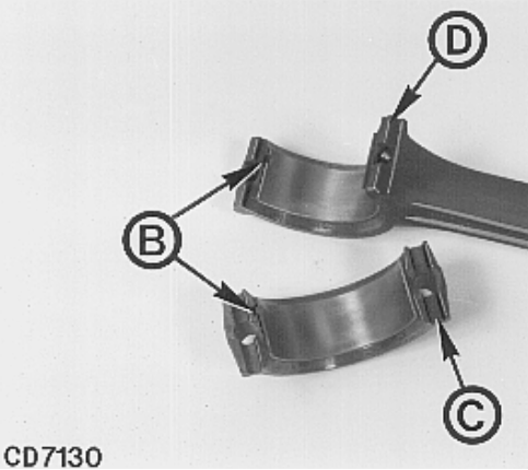
   3. Install bearing inserts, making sure small tangs (B) on
each half of the inserts fit in recess of rod and cap.

2017 JCB Service Parts Pro+Service Repair Download

 
4. Install cap so that large slot in cap (C) fits large tang
(D) on connecting rod.


5. Dip NEW connecting rod cap screws in clean oil and
tighten them alternately to following torques:
IMPORTANT: NEVER use connecting rod cap screws
more than once.
• 3029, 4039 and 6059 engines:
Initially tighten cap screws to 56 N·m (40 lb-ft)
• 4045 and 6068 engines:
Initially tighten cap screws to 66 N·m (50 lb-ft)


6. Torque-turn all cap screws 90—100 degrees. (See
next module).
CD,3274,G10,16 -19-20FEB92


2023年1月6日星期五

Cummins Fire Pump Drive Physical Engine Installation Guide

 This article mainly introduces  CFP83 SERIES Fire Pump Drive  Physical Engine 

     Cummins INSITE 8.7 Pro 2021 Electronic Service Diagnostic Software

Installation Guide
Location
Refer to Drawing CFP83 GEN in Section 13 for the general fire pump and engine layout.
Refer to the following drawings in Section 13 for the general fire pump engine power module assembly:


WARNING Do not operate a diesel engine where there are or can be combustible vapors. These vapors can be sucked through the air intake system and cause engine acceleration and overspeeding, which can result in a fire, an explosion, and extensive property damage. Numerous safety devices are available, such as air intake shutoff devices, to minimize the risk of overspeeding in which an engine, because of application, might operate in a combustible environment (from a fuel spill or gas leak, for example).
Cummins Engine Company, Inc. does not know how you will use your engine. The equipment owner and operator, therefore, are responsible for safe operation in a hostile environment. Consult your Cummins Authorized Repair Location for further information.
Install the fire pump engine in a sheltered environment protected from extremes of weather. Any enclosure must protect the water supply from freezing. Ensure that the engine and electrical components are not exposed to significant water dripping or sprays. Avoid installation in a dusty or dirty environment. Provide adequate physical protection from other physical damage as may be present in the specific location. (Refer to National Fire Protection Association NFPA20-2003 Chapter 11 for additional installation requirements for installations in the USA.)
Design the installation to meet the engine's mounting requirements. Refer to General Engine Data in Section o. Install the engine on a stable level foundation that is designed for the load and vibration of pump operation.
Install the engine with ample room for servicing of the engine, the pump, fuel supply, and support systems.
Ensure that the engine location is free of any risk of exposure to combustible vapors.

Cummins INLINE 6 Data Link Adapter Truck Diagnostic Tool


Physical Installation
Use the supplied lifting hooks on the engine to
position the engine.
Provide engine support as required to support
the wet weight specified in General Engine
Data in Section 10.
Position the engine as required for the interface
with the pump, piping, and electrical
connections.
Level the installation with shims as required.
Secure the engine to the support or floor.
Connect the exhaust piping


2023年1月3日星期二

Bobcat STEERING LEVERS Removal and Installation Guide

                              Bobcat 741_742_742B_743_743B_743DS STEERING LEVERS
Removal and Installation guide


2022 Bobcat Service Analyzer Diagnostic Software 90.00


NOTE:      Early production machines used 3-piece assembly.
Current production machines use 1-piece shield which
must be removed as a unit.
Remove the front panel

Remove the bolts and remove both side shields 00.


Remove the bolts from the steering lever shield (g & [Q].


Remove the steering linkage at the steering levers

Disconnect the auxiliary linkage from the right steering lever
lID


Remove the bolts (Item 1) from the pivot bearings 'Cl.
Installation: Tighten the bolts to 25-28 ft.-Ibs. (34-38 Nm)
torque.


2022 Bobcat Service Analyzer Diagnostic Software 90.00


Remove the steering lever assembly @.


Repairing the Steering Levers
Remove the rubber bushing and the Teflon bushing from the
steering levers.
Install the new rubber bushings into the steering levers using
two sockets and a vise ~l


2022 Bobcat Service Analyzer Diagnostic Software 90.00


Install the Teflon bushings on the steering levers [!!).


Install the two steering lever assemblies together ~.
Check the pivot bearings and replace as needed.


2023年1月1日星期日

JCB Excavator 3CX 4CX Changing the Oil and Filter Guide

                       JCB Excavator 3CX 4CX  Changing the Oil and Filter Guide


When draining JCB 760 Series Powershift gearboxes it is
recommended that the oil is drained through the cover plate
A to make sure that the debris collected in the transmission
sump is flushed out. Draining oil through the sump plug will
filter oil through the strainer and not flush out the debris.


                                 WARNING!
Make the machine safe before getting beneath it. Lower
the attachments to the ground; engage the parking
brake; remove the starter key, disconnect the battery.


JCB ServiceMaster 4 v22.9.3 [12.2022] Diagnostic Software Download and Installation


 1 Park the machine on firm level ground, apply the park
brake. Lower the loader arms, open the engine bonnet,
raise the loader arms and fit the safety strut. Lower the
excavator to the ground, switch OFF the engine and
remove the starter key.
2 Apply the parking brake and disconnect the battery,
remove the engine side panels.
3 Place a container of suitable size beneath the
transmission to catch the oil.
4 Remove bolts B. Pull off cover plate A and gasket C,
allow the oil to drain into the container. Be aware that
the oil may be hot.
Note: When the cover is removed oil will gush out. Keep to
one side when you remove the cover plate.


2017 JCB Service Parts Pro+Service Repair Download


5 Fit cover plate A and a new gasket C. Apply JCB
Threadlocker and Sealer to bolts B before fitting them.
Torque tighten the bolts to 28 Nm (20.5 lbf ft.).
6 Unscrew and remove the filter D. Fit the new filter:
6.1 Smear seal E with transmission oil.
6.2 Screw the filter on until it just contacts the filter
head.
6.3 Turn the filter at least another 3/4 of a turn.
7 Fill the system with new oil through the dipstick/filler F.
Do not fill past the top mark on the dipstick.
8 On completion check for oil leaks.
Note: Fit only a genuine supplied JCB filter, otherwise
damage to the system may be incurred through
contamination.

2022年12月28日星期三

John Deere engines Connecting Rod Bushing Replacement(TAPERED PIN-END CONROD) Guide

John-Deere30294039-40456059-6068-Engines Connecting Rod Bushing Replacement(TAPERED PIN-END CONROD)


07.2022 John Deere & Hitachi Parts ADVISOR Parts Catalog EPC(CF&AG&CCE)


Using JDG738 Connecting Rod Bushing Service Set,
proceed as follows.
1. Slide driver JDG738-1 (A) into one side of rod
bushing (C). Turn driver until taper on driver flange
matches up with taper on bushing.
2. Install receiver cup JDG738-3 onto opposite side of
rod bushing.
NOTE: Stud in cup keeps rod properly located on the
cup. Use JDG738-2 pilot ring (B) as a hollow
spacer when pressing bushing out of rod.
3. Using hydraulic press, push bushing out of rod until
driver and bushing fall into receiver cup


John Deere PayLoad encryptor-decryptor + KG 

4. Slide bushing (A) onto JDG738-1 driver (B) and
install JDG738-2 pilot ring (C) onto O-ring end of
driver.
5. Apply TY6333 grease* to:

 Outside diameter of bushing

Outside diameter of pilot ring

Inside diameter of rod pin bore


6. Insert driver into rod pin bore so pilot ring pilots in rod
bore and bushing taper aligns with taper on driver
flange. Align oil hole in bushing (D) with oil hole in end
of rod (E).
7. Install JDG738-3 receiver cup (F) onto opposite side
of rod so taper on rod aligns with taper on receiver cup.
8. Press bushing into rod until edge of bushing is flush
machined surface on connecting rod face.
IMPORTANT: Oil holes MUST be aligned. If holes are
not aligned, remove and discard
bushing then re-install a NEW bushing.
DO NOT attempt to reuse a bushing.
9. Have the new bushing reamed by a specialized
workshop to obtain an oil clearance of 0.020 to 0.056
mm (0.0008 to 0.002 in.) with piston pin.

2022年12月27日星期二

Komatsu of Engine Air Filter Moval and Installation Gudie

 This article mainly introduces  Komatsu WH716-1 of ENGINE AIR FILTER Removal and Installation

            Komatsu Forklift LinkOne EPC 11.2012 Spare Parts Catalog

                     
Removal
1 -Unscrew and remove the cap (1) from the surge tank (2).
2 -Loosen and remove the screws (3), remove the surge
tank (2), and position the tank aside.


3 -Loosen the clamps (4), (5) and disconnect the outside
air inlet hose (7) and engine intake hose (8) from the filter
(6)                                 Komatsu CSS Net EPC 05.2022


4 -Disconnect the air cleaner clogging sensor connector
(9)


5 -Loosen and remove the screws (10) together with washers and nuts and remove the filter (6)
Komatsu LinkOne Construction Parts Catalogue 2017

2022年12月25日星期日

JCB Excavator 3CX 4CX Changing the Coolant Guide

 This article mainly introduces JCB excavator 3CX 4CX   Changing the Coolant


                               WARNING!  
The cooling system is pressurised when the coolant is
hot. Hot coolant will burn you. Make sure the engine is
cool before checking the coolant level or draining the
system.


2017 JCB Service Parts Pro+Service Repair Download


1 Make sure the park brake is engaged and the
    transmission set to neutral. Lower the loader arms and
    backhoe to the ground, switch OFF the engine and
    remove the starter key.
2 Open the bonnet, see Engine Panels, Opening and
   Closing the Bonnet.
3 Carefully loosen cap A. Let any pressure escape.
   Remove the cap.
                                  CAUTION!   
Keep your face away from the drain hole when removing
the drain plug.
2-3-3-4
4 Remove drain plug C and let the coolant drain out.
   Make sure the drain hole is not blocked.
5 Disconnect the radiator hose at D and allow the coolant
   to drain. Flush the system using clean water.
6 Clean and refit plug C. Make sure it is secure.
   Reconnect the radiator hose
7 Use the necessary mix of clean, soft water and
   antifreeze, see Coolant Mixtures. Fill to the COLD/MIN
   level on coolant reservoir B.
8 Start the engine and run at idle to circulate the coolant,
   top up with coolant as necessary.
9 Refit the filler cap. Make sure it is tight.
10 Run the engine for a while, to raise the coolant to
   working temperature and pressure. Stop the engine.
   Check for leaks.
   Note: Make sure the cab heater control is in the hot
   position. This will ensure the coolant mixture circulates
   through the entire cooling system.


JCB ServiceMaster 4 v22.9.3 [12.2022] Diagnostic Software Download and Installation


How to relieve hydraulic pressure in the hydraulic circuit of a CAT excavator.

  How to relieve hydraulic pressure in the hydraulic circuit of 312D2 and 313D2 excavators   Steps to relieve pressure:   Caterpillar ET 202...