Translate

2023年2月20日星期一

How to Adjust Fuel Injection Pump and Governor of Yanmar Marine Diesel Engine

  YANMAR Model 3jh2 series  MARINE DIESEL NGINE Adjustment of Fuel Injection Pump and Governor
Yanmar Engine Diagnostic Service Tool Software

 
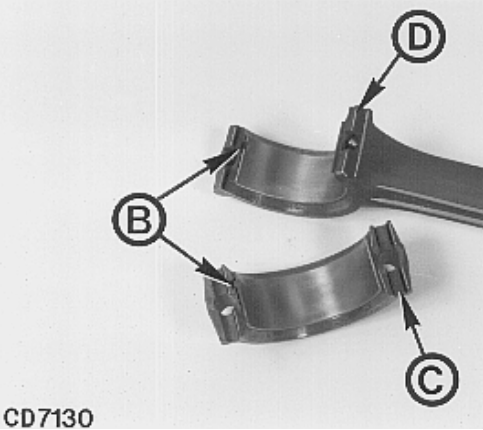
Adjust the fuel injection pump after you have completed reassembly. The pump itself must be readjusted with a special pump tester when you have replaced major parts such as the plunger assembly, roller guide assembly, fuel camshaft, etc. Procure a pump tester like the one illustrated below.
1-1Preparations
Prepare for adjustment of the fuel injection pump as follows:
(1) Adjusting nozzle assembly and inspection of injection starting pressure.


Prepare for adjustment of the fuel injection pump as follows:
(1) Adjusting nozzle assembly and inspection of injection starting pressure.


(2) Adjusting injection pipe.


For Yanmar Diesel Engine Agriculture Excavator Tractor Marine Generator Diagnostic tool
(3)Mount the fuel injection pump on the pump tester plat-


(4) Remove the control rack blind cover and fit the rack indicator.
Next, turn the pinion from the side of the pump until the control rack is at the maximurm drive side position, and set it to the rack indicator scale standard position.
Then make sure that the control rack and rack indicator slide smoothly.


(5) Check control rack stroke Make sure the rack position is at 11.5~ 12.5mm (0.4527
~ 0.4921in.) on the indicator scale when the governor control lever is set at the maximum operating position.
If it is not at this value, change the link connecting the govemor and control rack to adjust it.
NOTE: Links are availabe in 1mm (0.0394in. Jincrements.
(6) Remove the plug in the oil fill hole on the top of the governor case, and fill the pump with about 200cc of pump oil or engine oil.

(7) Complete fuel oil piping and operate the pump tester to purge the line of air.
(8) Set the pressure of oil fed from the pump tester to the injection pump at 0.2~0.3kg/cm2(2.84~4.26 In/in.2).


4-2 Adjustment of top clearance Adjust the top clearance(the clearance between the top of plunger and the top of barrel with the cam at top dead center) of each cylinder plunger to bring it to the specified value by changing the thickness of the shims.


(1) Place the top clearance gauge on a level surface and set the gauge to zero.


(2) Remove the injection pump delivery retainer, take out the delivery valve assembly, insert the top clearance gauge and tighten by hand.

Yanmar Engine Diagnostic Service Tool Software
(3) Turn the camshatt, and bring the cam to the top dead center while watching the gauge needle.

(4) Read the gauge at this position, and adjust until the clearance is at the specified value by changing ad.
Justing shims.
Tighten the adjusting screw after completing adjust.
ment.

(Greater shim thickness decreases top clearance and smaller shim thickness increases top clearance).


NOTE: Adjust while watching gauge, and then tighten.
(5) After adjustment is completed, insert the delivery valve assembly and tighten the delivery retainer. kom(h-.b)
3.5~4.0
Deivery retainer tightening torque |(2531~2893)
Repeat the above procedure to adjust the top clearance of each cylinder.
4-3Adjusting of injection timing After adjusting the top clearance for all cylinders, check/adjust the injection timing.


Yanmar Heavy Equipment EPC 11.2009 

(1) Set the governor control lever to the operating position and fix(bring plunger to the effective injection range), turn the camshaft clockwise, and check the injection starting time (FID) of cylinder No.1(start of discharge of fuel from the delivery retainer).
Cylinder no.| Count from the drive side Direction of rotation | Right looking from drive side
(2) In the above state, set the tester needle to a position easy to read on the flywheel scale, and check the injec.
tion timing several tirmes by reading the flywheel scale, according to the injection order.


(3) Readjust the top clearance of cylinders that are not within the allowable deviation(increasing adjusting shim thickness makes injection timing faster, and decreasing makes it slower).
The change in injection timing effected by adjusting shims is as follows:


(4) When you have readjusted top clearance, make sure it is within allowable values after completing adjustment.
mm(in.) Allowable top clearance0.3(0.0118)
NOTE:1. All cylinders must be readjiusted it any one shows less than the allowable value.
2. If the top clearance is less than the allowable value, the plunger will hit the delivery valve or the plunger flange will hit the plunger barrel.


(1) Mount the pressure gauge to the delivery retainer of the cylinder to be tested.


(2) Set the governor control lever to the stop position, operate the injection pump at about 200 rpm, and make sure that the pressure gauge reading is 500 kg/cm?
(7110 lb/in.7) or more while lightly moving the control pinion gear towards full throttle(drive side) from the pump.
Replace the plunger if the pressure does not reach this value.
(3) Immediately release the gear after the pressure rises to stop injection.
At the same time, check to see that oil is not leaking from the delivery retainer or fuel injection piping, and that there is no extreme drop in pressure.
4-5Dellvery valve pressure test
(1) Perform the plunger pressure test in the same way, bringing the pressure to about 120 kgl/cm2(1706 tb/in.2), and then stopping injection.


(2) After pressure rises to the above value, measure the time it takes to drop from 100~ 90 kg/cm2(1422 ~2702
Ib/in.).
100→90kg/cm25 seconds
(1422~1280 ib/in.2)(to drop 10 kg/cm"(142 lb/in.)
If the pressure drops faster than this, wasli the delivery valve, and retest. Replace the delivery valve if the pressure continues to drop rapidly.

4-6Adjusting Injection volume(uniformity of each cylinder)
The injection volume is determined by the fuel injection pump rpm and rack position. Check and adjust to bring to specified value.
4-6.1 Measuring injection volume
(1) Preparation Set the pump rpm, rack position and measuring stroke to the specified value and measure: Pump RPM1800pm Pump rotating direction Right looking from drive side Fass ingicator scale 7mm (o.2756 i)
reading Remove the rack stop bolt behind the pump and screw in the rack fixing bolt to fix the rack.


(2) Measuring injection volume Measure the Injection volume at the standard stroke, and adjust as follows if it is not within the specified value.
Measuring stroke 1.000t Specified injection volume |See injection pump at standard rack position |service data Nonuniformity of cylinders 3%
4-6.2 Adjustment of injection volume Measure the injection volume in measuring cylinders for each cylinder, and adjust if necessary to obtain the specified values.
(1) Push the control rack all the way to the drive side, stop with the rack fixing bolt, and loosen the pinion/sleeve fixing bolt 1/3 of a revolution.

(2) When the control sleeve is turned to the right or left, the plunger is turned through the same angle to in-
crease or decrease injection volume.
The injection volume is increased when the control sleeve is turned in the-direction and decreased when turned in the-direction in the following figure.

(3) Measure the injection volume of each cylinder again.
Repeat this process until the injection volume for every cylinder is the same(within the specified limit).
(4) Next, measure the injection volumes under different conditions, and make sure the injection volume for every cylinder is within the specifications.
Replace the plunger if the injection volume is not within specifications.
NOTE: See adjustment data for the speciied injection volume value at other measuring points.
(5) After completing measurement, firmly tighten the piston/sleeve fixing screw.
(6) If not aligned with the match mark, make a new match mark.
4-7Adjustment of governor
4-7.1Adjusting fuel limit bolt
(1) Adjust the tightness of the fuel limit bolt to bring the rack position to the specified value (R) with the governor control lever all the way down towards the fuel increase position, while keeping the pump at rated rpm N.


(2) Measure fuei injection volume at rack position (Ri).
Tightening of fuel limit bolt.
(3) If the injection volume is at the specified value, tighten the fuel limit bolt lock nut at that position.
4-7.2 Adjusting RPM limit bolt
(1) Gradualy loosen the governor control lever while keep ing the pump drive condition in the same condition as when the fuel limit bolt was adjusted, and adjust the tightness of the RPM limit bolt to the point where the rack position just exceeds the specified value(Ri).


(2) Check maximum RPM at no load Further increase rpm, and make sure that rack position
(R2=R1-L) corresponding to maximum rpm at no load is within specified value(Nz).
N9.0ad B&; RPM 1950rom YPUmD RPi
4-7.3Adjusting idling
(1) Maintain the pump rpm at specified rpm (N).

Yanmar Engine Diagnostic Service Tool Software

(2) Measure the injection volume while lowering the governor control lever to the Idling position, and adjust the position of the control lever with the idting adjust-
ment bolt to bring it to the specified value.
Measuing 5trgke|1000 st Idling injection volumeSee irjection purmp survice dra
4-7.4 Check injection volume when starting
(1) Make sure the control rack moves smoothly while gradually reducing idling rpm.
(2) Next, fix the governor control lever at the full load position with the pump at the specified rpm(Na). Make sure that control rack is at the maximum rack position
(11.05~12.05).
Measure the injection volume and check to make sure it is within the specified value.
Pump pm (N)200rpm Rack indicator scale |11.5~12.5mm(0.4527~0.4921 in.)
Measuring stroke|1000st Injection volurme|See injection pumo swrvice data Checking injection stop Drive the pump at rated rpm(N1) and standard rack position(R1) with the governor control lever at the fullload position, operate the stop lever on the back of the governor case, and make sure that injection to all cylinders is stopped.
NOTE: Be sure to remove the rack fixing bolt when doing this.

2023年2月16日星期四

How to Deal Hino Drive Shaft Failure

    How to deal hino bus drive shaft failure

Symptom:
Abnormal vibration
when driving


Possible cause :
Looseness of universal joint yoke and
flange tightening nuts.
Excessive propeller shaft runout Worn or damaged universal joint Incorrect phasing of the yokes


Remedy/Prevention:
Tighten the nuts.
Rpl
Replace the universal joint.
at tephasingarrsrretly.


PROPELLER SHAFT:


IMPORTANT
POINT-DISMOUNTING DISCONNECT THE PROPELLER SHAFT FROM THE FLANGE ON THE DIFFERENTIAL AND TRANSMISSION.
1.Draw the match marks on the flange and yoke.
2.Remove nuts and bolts.


IMPORTANT POINT-DISASSEMBLY DISASSEMBLE THE UNIVERSAL JOINT.
1.
Remove the retainer ring from the yoke.
2.
Position the yoke under the arbor press and push universal joint partially out of the yoke lug.
The bearing is protruded from the yoke.
3.
Place the propeller shaft assembly in a vice, gripping protrud-
ing bearing with vice. Tap on the yoke in area shown to achieve removal of universal joint bearing.
4.
Place the yoke under arbor press with opposite side of universal joint spider in up position and place small push tool on the universal joint spider end.
5.
Press the opposite bearing out of the yoke lug.
6.
Remove the spider from the yoke.
7.
Remove the bearing from the yoke lug.
NOTE: Keep the original location of the bearings, thrust washers, spider and retainer rings in mind. These parts have to be replaced in the same position as before disassembly when re-assembly.


DISASSEMBLE THE DUST SEAL.
1. Remove the sliding yoke.
2. Remove the dust seal.


IMPORTANT POINT-ASSEMBLY ASSEMBLE THE UNIVERSAL JOINT BEARINGS.
1. After the universal joint bearing assemblies are thoroughly clean, apply clean lubricant to the rollers.
2. Check each bearing for missing rollers.
NOTE: Remove the stale grease from the bearing cage. Lubricate grease containing molybdenum disulfide on the needle roller, seal lip and the both surface of thrust washer.


INSTALL THE SPIDER AND UNIVERSAL JOINT BEARINGS INTO THE YOKES.
1. Put the spider into the yoke and then set the universal joint bearings on the yoke.
NOTE: When assembling the universal joint spider to the sliding yoke, position the lubrication fitting so that it is to the yoke side as shown in figure.


2.Press the universal joint bearings into the yokes.
NOTE:O Play attention not to damage the seal lip of the universal joint bearing when installation.
o Align the phasing arrow on the universal joint yoke and the phasing arrow on the sliding yoke.


CHECK THE STARTING TOROUE OF THE UNIVERSAL JOINT USING A SPRING BALANCER.
Assembly Standard:15-50 kg-cm(13-43 lb. in)
1. If the torque is below 15 kg-cm(13 lb. in), replace the thrust washer to the thicker one.
2. If the torque is below 50kg-cm (43 lb. in), replace the thrust washer to the thinner one.


ASSEMBLE THE SLIDING YOKE AND PROPELLER SHAFT SUB ASSEMBLY.
1.Remove the stale grease from the spline of the propeller shaft.
2.Install the new dust seal on the shaft by pushing it in the seal groove.
3.Apply the grease containing molybdenum disulfide on the spline and sliding area of the dust seal.


4. Align the phasing arrow on the shaft sub assembly and the phasing arrow on the sliding yoke.
5. After assembling the propeller shaft, check the phasing arrow as whon in the figure.
6. Adjust the direction of lubrication fitting for sliding yoke side and propeller shaft side as shown in figure.


IMPORTANT POINT-MOUNTING CONNECT THE PROPELLER SHAFT TO THE FLANGE ON THE DIFFERENTIAL AND TRANSMISSION.
1.Align the match marks on the flange and yoke.
2.Tighten the bolts and nuts.
3.Lubricate the universal joints and sliding spline.
Grease:Refer to recommended lubricants list.


2023年2月3日星期五

How to reassemble yanmer marine diesel engine fuel injection pump

yanmer 3JH2 Series Reassembly of fuel injection pump


 Preparation:

  After inspection, put all parts in order and clean.
See Inspection of Fuei Pump for inspection procedure.
(1) Put in the plunger barrel from the top of pump.

Yanmar Engine Diagnostic Service Tool Software

NOTE: Make sure the barrel key groove is fitted properly to the barrel stop pin.
(2) Place the delivery valve assembly, packing, spring and stopper from the top of the pump, in that order.


NOTE: Replace the delivery valve packing and O-ring.

(3) Place the control rack, and tighten the control rack stop bolt.


NOTE: 1. Do not forget the rack aux. spring.
2. Make sure the rack moves smoothly through a full cycle.
(4) Piace the rack set screw (using the special tool) in the rack stop bolt screw hole to fix the rack.
(5) Looking from the bottom of pump, align the match marks on the rack and pinion.
Control ck Pincti


(6) While holding the pinion with one hand and keeping it aligned with the match mark, fit in the sleeve, and light-
ly tighten the small pinion screw.


NOTE: Fitting of sleeve; Face towards small pinion screws and align with match mark.
Pinion/sleeve match mark Match mark


(7) Mount the plunger spring upper rest.


NOTE: 1. Be sure to mount the upper rest with the hollow side facing down.
2. Recheck to make sure that the rack moves easily.
(8) Mount the plunger spring.
(9) Mount the lower rest on the head of the plunger, and fit the plunger in the lower part of pump while align-
ing the match marks on the plunger flange and the sleeve.


NOTE: If the plunger is mounted in the opposite direction, the injection volume will increase abnormally and cannot be adjusted.

(10) Insert the plunger spring support plate between the plunger spring seat B (lower) and fuel pump, by put-
ting the handle of a hammer in the lower part of pump and pushing the roller guide up.


NOTE: 1. Face the roller guide stop groove upwards, and align it with the stop screw hole on the pump.


2. Check the movement of the rack. The plunger spring may be out of place if the movement is heavy -insert a screwdriver and bring it to the correct position.
3. When replacing the roller guide assembly, tit shims and lightly tighten: Standard shim thickness
1.2 mm (0.0472 in.)
Part code number
129155-51600
(11) Make sure that the roller guide stop groove is in the correct position, and tighten the roller guide stop bolt.


(12) Fit the bearings to both ends of the camshaft, and in sert from the drive side by tapping lightly.


NOTE: Turn the pump upside down, and tap in the cam-
shaft while moving the roller guide to the plunger spring side.
(13) Fit the oil seal on the inside of the bearing retainer and mount the bearing retainer.


NOTE: Coat the camshaft and oil seal with oil to prevent the oil seal from being scratched.
(14) Fix the pump, lightly tap both ends of the cam shaft with a wooden hammer, and adjust the cam shaft side clearance with the adjustment shims while checking with a side clearance gauge.

yanmar-diesel-engine-agriculture-excavator-tractor-marine-generator-diagnostic-tool/
(15) Mount the fuel pump side cover.
(16) Tap in the camshaft wood ruff key.
(17) Turn the camshaft, and pull out the plunger spring support plate.


NOTE: Fit double nuts to turn the camshaft.


(18) Tighten the delivery valve retainer.


NOTE: 1. Tighten the retainer as far as possible by hand-
if the bolt gets hard to turn part way, the packing or delivery vaive are out of place. Remove, cor-
rect, and start tightening again.
2. Overtightening can result in malfunctioning of the rack.
(19) Fit the delivery retainer stop and tighten the stop bolt.


(20) Mount the fuel feed pump


NOTE: Refer to the instructions for reassembly of the fuel feed pump.

2023年1月23日星期一

John Deere Engines Piston and Connecting Rod Installation Guide

 John Deere engines   piston  and   connecting rod installation Guide


NOTE: Pistons must be installed in the cylinder liner
from which they were removed.


1. Coat pistons and rings with clean engine oil. Install
pistons in liners, using JDE84 piston ring compressor.
NOTE: Make sure that “FRONT” mark (A) on the top of
each piston faces toward front end of cylinder
block.

JCB ServiceMaster 4 v22.9.3 [12.2022] Diagnostic Software Download and Installation


2. Push piston down until top ring is in liner.


   3. Install bearing inserts, making sure small tangs (B) on
each half of the inserts fit in recess of rod and cap.

2017 JCB Service Parts Pro+Service Repair Download

 
4. Install cap so that large slot in cap (C) fits large tang
(D) on connecting rod.


5. Dip NEW connecting rod cap screws in clean oil and
tighten them alternately to following torques:
IMPORTANT: NEVER use connecting rod cap screws
more than once.
• 3029, 4039 and 6059 engines:
Initially tighten cap screws to 56 N·m (40 lb-ft)
• 4045 and 6068 engines:
Initially tighten cap screws to 66 N·m (50 lb-ft)


6. Torque-turn all cap screws 90—100 degrees. (See
next module).
CD,3274,G10,16 -19-20FEB92


2023年1月6日星期五

Cummins Fire Pump Drive Physical Engine Installation Guide

 This article mainly introduces  CFP83 SERIES Fire Pump Drive  Physical Engine 

     Cummins INSITE 8.7 Pro 2021 Electronic Service Diagnostic Software

Installation Guide
Location
Refer to Drawing CFP83 GEN in Section 13 for the general fire pump and engine layout.
Refer to the following drawings in Section 13 for the general fire pump engine power module assembly:


WARNING Do not operate a diesel engine where there are or can be combustible vapors. These vapors can be sucked through the air intake system and cause engine acceleration and overspeeding, which can result in a fire, an explosion, and extensive property damage. Numerous safety devices are available, such as air intake shutoff devices, to minimize the risk of overspeeding in which an engine, because of application, might operate in a combustible environment (from a fuel spill or gas leak, for example).
Cummins Engine Company, Inc. does not know how you will use your engine. The equipment owner and operator, therefore, are responsible for safe operation in a hostile environment. Consult your Cummins Authorized Repair Location for further information.
Install the fire pump engine in a sheltered environment protected from extremes of weather. Any enclosure must protect the water supply from freezing. Ensure that the engine and electrical components are not exposed to significant water dripping or sprays. Avoid installation in a dusty or dirty environment. Provide adequate physical protection from other physical damage as may be present in the specific location. (Refer to National Fire Protection Association NFPA20-2003 Chapter 11 for additional installation requirements for installations in the USA.)
Design the installation to meet the engine's mounting requirements. Refer to General Engine Data in Section o. Install the engine on a stable level foundation that is designed for the load and vibration of pump operation.
Install the engine with ample room for servicing of the engine, the pump, fuel supply, and support systems.
Ensure that the engine location is free of any risk of exposure to combustible vapors.

Cummins INLINE 6 Data Link Adapter Truck Diagnostic Tool


Physical Installation
Use the supplied lifting hooks on the engine to
position the engine.
Provide engine support as required to support
the wet weight specified in General Engine
Data in Section 10.
Position the engine as required for the interface
with the pump, piping, and electrical
connections.
Level the installation with shims as required.
Secure the engine to the support or floor.
Connect the exhaust piping


2023年1月3日星期二

Bobcat STEERING LEVERS Removal and Installation Guide

                              Bobcat 741_742_742B_743_743B_743DS STEERING LEVERS
Removal and Installation guide


2022 Bobcat Service Analyzer Diagnostic Software 90.00


NOTE:      Early production machines used 3-piece assembly.
Current production machines use 1-piece shield which
must be removed as a unit.
Remove the front panel

Remove the bolts and remove both side shields 00.


Remove the bolts from the steering lever shield (g & [Q].


Remove the steering linkage at the steering levers

Disconnect the auxiliary linkage from the right steering lever
lID


Remove the bolts (Item 1) from the pivot bearings 'Cl.
Installation: Tighten the bolts to 25-28 ft.-Ibs. (34-38 Nm)
torque.


2022 Bobcat Service Analyzer Diagnostic Software 90.00


Remove the steering lever assembly @.


Repairing the Steering Levers
Remove the rubber bushing and the Teflon bushing from the
steering levers.
Install the new rubber bushings into the steering levers using
two sockets and a vise ~l


2022 Bobcat Service Analyzer Diagnostic Software 90.00


Install the Teflon bushings on the steering levers [!!).


Install the two steering lever assemblies together ~.
Check the pivot bearings and replace as needed.


2023年1月1日星期日

JCB Excavator 3CX 4CX Changing the Oil and Filter Guide

                       JCB Excavator 3CX 4CX  Changing the Oil and Filter Guide


When draining JCB 760 Series Powershift gearboxes it is
recommended that the oil is drained through the cover plate
A to make sure that the debris collected in the transmission
sump is flushed out. Draining oil through the sump plug will
filter oil through the strainer and not flush out the debris.


                                 WARNING!
Make the machine safe before getting beneath it. Lower
the attachments to the ground; engage the parking
brake; remove the starter key, disconnect the battery.


JCB ServiceMaster 4 v22.9.3 [12.2022] Diagnostic Software Download and Installation


 1 Park the machine on firm level ground, apply the park
brake. Lower the loader arms, open the engine bonnet,
raise the loader arms and fit the safety strut. Lower the
excavator to the ground, switch OFF the engine and
remove the starter key.
2 Apply the parking brake and disconnect the battery,
remove the engine side panels.
3 Place a container of suitable size beneath the
transmission to catch the oil.
4 Remove bolts B. Pull off cover plate A and gasket C,
allow the oil to drain into the container. Be aware that
the oil may be hot.
Note: When the cover is removed oil will gush out. Keep to
one side when you remove the cover plate.


2017 JCB Service Parts Pro+Service Repair Download


5 Fit cover plate A and a new gasket C. Apply JCB
Threadlocker and Sealer to bolts B before fitting them.
Torque tighten the bolts to 28 Nm (20.5 lbf ft.).
6 Unscrew and remove the filter D. Fit the new filter:
6.1 Smear seal E with transmission oil.
6.2 Screw the filter on until it just contacts the filter
head.
6.3 Turn the filter at least another 3/4 of a turn.
7 Fill the system with new oil through the dipstick/filler F.
Do not fill past the top mark on the dipstick.
8 On completion check for oil leaks.
Note: Fit only a genuine supplied JCB filter, otherwise
damage to the system may be incurred through
contamination.

How to relieve hydraulic pressure in the hydraulic circuit of a CAT excavator.

  How to relieve hydraulic pressure in the hydraulic circuit of 312D2 and 313D2 excavators   Steps to relieve pressure:   Caterpillar ET 202...