Translate

2023年5月27日星期六

Disassembly and inspection method of main components of Hitachi excavator diesel engine --- cylinder head cover

Disassembly and inspection of main part of Hitachi excavator ZX200-3 excavator 4HK1 diesel engine

 cylinder head cover (1) Structure (1) The cylinder head cover assembly of 4HK1 diesel engine is shown in Figure 3-3-1. 

2021 Hitachi MPDr 3.15.0.0 MaintenancePRO Download and Install Service 


   (2) The cylinder head cover assembly of 6HK1 diesel engine is shown in Figure 3-3-2. 


   Hitachi Excavator Diagnostic Tool for ZX-5A ZX-5B ZX-5G ZX-1 ZX-3 Series

 (2) Disassembly

  (1) Remove the cylinder head cover. See Figure 3-3-3 for the cylinder head cover of 4HK1 diesel engine, and Figure 3-3-4 for the cylinder head cover of 6HK1 diesel engine. 


   Hitachi Workshop Service Manual 2019 PDF Download

 (2) Remove the gasket.

  (3) Remove the injector harness connector. 

 (4) Remove the cylinder head cover. See Figure 3-3-5 for the cylinder head cover of 4HK1 diesel engine and Figure 3-3-6 for the cylinder head cover of 6HK1 diesel engine  


 (5) Remove the gasket. 

       (3) Installation 

 (1) Install the gasket on the lower cover. 

 (2) Install the cylinder head cover, tighten the cylinder head cover, tightening torque: 18N m (4HK1 diesel engine), 13N m (6HK1 diesel engine).  

(3) Install the fuel injector harness connector, and insert it completely until the lock claw is lifted. 

 (4) Install the gasket to the cylinder head cover. 

 (5) Install the cylinder head cover, see Figure 3-3-7 for the installation of the cylinder head cover for the 4HK1 diesel engine, and 3-3-8 for the installation of the cylinder head cover for the 6HK1 diesel engine. Tighten the bolts in the order shown in the figure, tightening torque: 18N.m (4HK1 diesel engine), 13N.m (6HK1 diesel engine). 

   Hitachi PartsManager Pro 2016


2023年5月20日星期六

Introduction to the Structural Features of SAA6D125E-3 and SAA6D107E-1 Diesel Engines for Komatsu Excavators (PC400-7 and PC200-8)

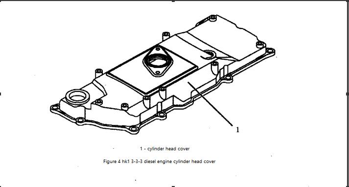
 (1) Overall structure diagram The structure of SAA6D125E-3 diesel engine is shown in Figure 2-3-1, and the structure of SAA6D107E-1 diesel engine is shown in Figure 2-3-2.

Komatsu CSS Net EPC 05.2022 


Komatsu Forklift LinkOne EPC 11.2012 Spare Parts Catalog
    (1) SAA6D125E-3 diesel engine complies with strict emission regulations: US EPA standard (2001 regulation), European regulation 2002, Japanese construction equipment regulation 2003, it is a diesel engine with high performance, high efficiency, low fuel consumption and low noise,
Improved exhaust color, improved acceleration. 

 (2) SAA6D125E-3 diesel engine and SAA6D107E-1 diesel engine are both in-line, 6-cylinder, water-cooled, direct-injection diesel engines. 

 (3) SAA6D125E-3 diesel engine and SAA6D107E-1 diesel engine adopt electronically controlled common rail fuel injection system, which injects high-pressure fuel at a pressure of 118MPa, which can provide the best injection control to match the speed and load, thereby improving Diesel engine emission performance, reducing fuel consumption and noise. 

 (4) The piston is made of high-quality steel, cast in a vibratory cooling furnace, and has the lowest thermal expansion in Komatsu tradition, which improves the reliability and life of the diesel engine. 

 (5) SAA6D125E-3 diesel engine and SAA6D107E-1 diesel engine adopt electronically controlled common rail fuel injection system and the design of optimal divergence characteristics at low temperature startup, which improves startup performance and reduces white smoke emission. 

 (6) The turbocharger used on the 125E-2 diesel engine is improved, so that the air supply cycle part can control the impact at the end of the compressor, so that the performance is optimal, the speed range from low speed to high speed is wider, and the fuel consumption is lower .

  (7) The thickness of the top surface of the cylinder block is increased, which can prevent deformation after long-term operation and make remanufacturing easier. In addition, by increasing the rigidity of the main reinforcement, the rigidity of the main body is improved, the deformation and vibration under load are reduced, and the generation of various noises is prevented. 

 (8) The size of the fuel supply pump of the electronically controlled common rail fuel injection system is 1/3 of the fuel supply pump of the ordinary in-line fuel injection system. In addition, the flange is used instead of the mounting seat, and it is tightly connected with the timing gearbox, thereby reducing noise.

  (9) The air filter is changed from ordinary end face seal to radial seal to prevent dust from entering and damaging parts. Additionally, a 5-segment display-type air filter clogging sensor provides accurate information on cleaning times.  

(10) The oil filter is a filter that combines high performance and high efficiency.

Komatsu LinkOne Construction Parts Catalogue 2017 

(11) The fuel filter is a special fuel filter with high performance and high efficiency, which can filter out small particles of dirt and protect the electronically controlled common rail fuel injection system. 

 (12) If the electronic control unit judges that the diesel engine is working abnormally, it will issue a warning and the system will switch to the emergency escape mode. 

 (13) After starting the diesel engine at a very low temperature, if the diesel engine speed suddenly increases, the overload will apply excessive load to the bearing before the lubrication is sufficient, which will reduce the service life of the diesel engine, especially the overload will damage Non-locating bearings for turbochargers. In order to prevent this situation, a turbo protection system is installed to limit the diesel engine speed.

2023年5月4日星期四

Introduction of Hitachi ZAXIS70/70LC Excavator Engine Control System

 
Introduction of  Hitachi ZAXIS70/70LC Excavator Engine Control System

A microcomputer built into the main controller (MC) monitors and controls all machine operations. The MC receives signals from the engine control knob and various other sensor switches. The MC then processes these signals and issues control signals to start the EC motor and various solenoid valves. The microcomputer control operation is as follows.
2021 Hitachi MPDr 3.15.0.0 MaintenancePRO Download and install service


1. Engine Control
The engine control system includes by combination: engine control knob control, E mode control, automatic idle speed control; optional ML (crane mode) engine speed limit control and engine learning control. The layout of the engine control system is shown in Figure 2-1.


2. Engine control knob control
Engine control knob control function: Control the engine speed according to the rotation angle of the engine control knob and reduce the engine speed by 100r/min when all joysticks are in the neutral position to reduce fuel consumption and noise. Operation: MC drives the governor lever according to the turning angle of the engine control knob to adjust the engine speed.
TIP: Even when the control knob is turned to the full speed position, the governor lever does not make contact with the full speed stop. With all joysticks in neutral (travel and nose attachment/swing sensors off)
After about 1 second, MC drives the EC engine to reduce the engine speed by 100r/min from the maximum speed.
The engine speed drops 100r/min from the maximum speed. Therefore, when the engine speed set by the engine control knob is already lower than the maximum speed of 100r/min, the engine speed remains unchanged. This engine speed deceleration control works regardless of whether the automatic idle speed control works. High and low idle speed control ranges are shown in Figure 2-2. The engine control knob controls are shown in Figure 2-3.

                                     Hitachi PartsManager Pro 2016


The angle of rotation decreases proportionally.
The E-mode control diagram is shown in Figure 2-5.

4. Automatic idle speed control
engine control
knob position
Automatic idle speed control function: when all joysticks are in the neutral position
, reduce engine speed to reduce fuel consumption and noise levels.
Figure 2-4 Engine speed drops at a constant specified rate
Automatic idle speed control operation: about 3.5s after all joysticks return to the neutral position, MC drives the EC motor, as shown in Figure 2-6, to reduce the engine speed to the automatic idle speed. As long as the joystick is operated (travel and/or front attachment, swing pressure sensor on) the MC drives the EC motor to increase the engine speed to the original engine speed (set by the engine control knob). Conditions under which the automatic idle system does not work:
1) Joystick: When operating (travel, swing, or front attachment joystick when the pilot sensor is on).
2) Power mode switch: when E mode is converted into P mode or P mode is converted into E mode.
3) Engine Control Knob: When changing the engine speed.
The automatic idle speed control is shown in Figure 2-7.

Hitachi Workshop Service Manual 2019 PDF Download
5. Idle acceleration control
Idling Acceleration Control Function: When the engine is running at a low speed, it prevents the engine from vibrating irregularly.
Idle speed acceleration control operation: as shown in Figure 2-8, when the engine is running at a speed between low idle speed and idle speed acceleration, when the travel or front-end accessory function is operated, MC drives the EC motor to make the engine speed idle speed acceleration control as shown in Figure 2 -9 shown.


6. Engine Learning Control
Engine Learn Function: Enter Governor Lever Stop in STOP
and FULL (full speed) side position as standard data to control the engine.
Engine learning operation: As shown in Figure 2-10, when the learning switch in the rear console is turned to the engine learning position, the EC motor is driven sequentially by signals from idle speed to full speed and to stop position. The EC sensor detects the position of the stoppers of the speed control lever on the FULL (full speed) and STOP (stop) sides and sends the stopper position signals to the MC, which stores these signals in its memory. Engine learning control is shown in Figure 2-11.
TIP: If repair work is done, be sure to perform an engine study. After performing the engine learning, use Dr.EX to check whether the engine learning has been carried out correctly.
When the battery is replaced, engine learning is not required.


7. Valve control
1. Travel motor swash plate angle control
Valve control function: select the walking speed in fast or slow mode.
2. Valve control operation
Slow mode: When the travel mode switch is in the SLOW (slow) position, MC will close the travel mode solenoid valve. The travel mode solenoid valve blocks the travel motor swash plate angle control oil pressure. Therefore, the travel motor swash plate angle increases, reducing the travel motor speed.
Fast mode: When the travel motor switch is set to the FAST (fast) position, MC will open the travel mode solenoid valve. The travel mode solenoid valve provides swash plate angle control oil pressure to the travel motor. Therefore, the angle of the travel motor swash plate is reduced, and the speed of the travel motor is increased.


Hitachi Excavator ZX-7 Service Repair Workshop Manual 2021 PDF
8. Walking alarm control
Walking alarm control works only when optional parts are installed. Walking alarm control function: the buzzer sounds when walking.
Walking alarm control operation: When performing a walking operation, the pressure sensor (walking) sends a signal to the MC. As soon as this signal is sent out, the MC outputs a signal to the walking alarm device to sound the buzzer.
Tips: After continuous walking for 13s or more, operating the buzzer release switch will disable the buzzer.
Walking alarm control is shown in Figure 2-13.
9. Slewing alarm control
The slewing alarm control works only when the option is installed.
Slewing alarm control function: During the slewing operation, the buzzer will sound while the indicator light is turning.
Swing alarm control operation: When performing a swing operation, the pressure sensor (swing) sends a signal to the MC. As soon as this signal is sent out, the MC outputs a signal to the slewing alarm device, sounds the buzzer and rotates the indicator light.
Note: Operating the buzzer release switch will disable the buzzer.
The rotation alarm control is shown in Figure 2-14.


2023年4月25日星期二

How to remove New Holland gearbox gear

 How to remove New Holland b115 gearbox gear

CNH DPA5 Adapter New Holland Heavy Duty mechanical Diagnostic Tool – full chips

INPUT SHAFT DISASSEMBLY (FRONT
SUPPORT END)
IMPORTANT: When using a bearing puller be very
careful to ensure it does not touch the tip of the gear
teeth as they may become chipped or broken.


1.  Support the shaft vertically (rear support end) in
a soft jawed vice and remove the sealing ring. At￾tach a 3 legged puller (1), to the underside of the
forward primary gear (2) and remove the gear
hub, needle bearings and spacer, thrust washer,
and bearing from the shaft.

NOTE: Prior to removal of the snap ring the wear fac￾tor of the clutch plates should can be checked.
Measure the distance between the face of the top
plate to to underside of retainer, approx. dimensions:
When new Approx. 2.22--4.93mm (0.08--0.19in)
When run in Approx. 5.64--8.35mm (0.22--0.32in)
Anything exceeding or close to 8.35mm should be
considered as worn and replaced with new.


2.  Release the snap ring (1), retaining the clutch
pack drive rings and remove from the clutch
housing.
The discs must be flat and not discoloured in any
way, if in doubt renew the discs.

3.  Using a press and tool NH 21 102 (1), compress
the clutch piston spring (2) to enable release of
the circlip (3). Carefully release the press pres￾sure on the spring. Remove the circlip, washer
and spring.

42 SECTION 21 -- TRANSMISSIONS -- CHAPTER 1
05/2003

4.  To remove the piston blank off the oil feed holes
that are not required and carefully apply air pressure to the forward clutch oil feed hole (1) in the
middle ring sufficiently to push the piston out
against seal resistance.


5.  The piston seals should be removed and discarded prior to re--assembly.
Inspect all parts for scoring wear marks and or discolouration, replace suspect parts as necessary.

2023 CASE New Holland Electronic Service Tools (CNH EST v9.8) Engineering Diagnostic Software

 
NOTE: The grove depth on the friction disc when
new is 0.38mm (0.014in) and is acceptable down to
0.10mm (0.004in). However any depth close to or
below 0.10mm (0.004in) when a teardown has taken
place should be considered as worn and replaced
with new.


INPUT SHAFT RE--ASSEMBLY (FRONT
SUPPORT END)
With the shaft supported vertically (in a soft jawed
vice), re--assembly is in reverse order of disassembly, ensure all metallic parts are liberally coated in
clean transmission oil before fitting.

6.  The internal and external piston seals require replacing, before assembly, soak seals in luke
warm water prior to fitting. Carefully refit the inner
‘O’-- ring and then the gland seal. The outer ‘O’--
ring can now be fitted along with the outer gland
seal.

7. Lubricate the piston seal and carefully place the
piston back into the clutch housing until fully
seated. Re--assemble the piston spring, washer
and compress using tool no #380000679 suffi￾ciently to allow refitting of the circlip and place the
thrust washer in position.

IMPORTANT: Soak new clutch friction discs in clean
new oil for a minimum of 3 hours

8. Continue to refit the clutch discs (6 thin steel with
1 thick retaining plate) and (6 friction plates) back
into the hub, steel first, followed by friction and
then repeat steel, friction. The final steel plate to
be fitted is the thicker retaining plate that the
snap ring seats onto. Refit the snap ring into the
groove of the clutch hub.


9. Once the gear is assembled into the clutch plates
the needle bearings and spacer can be as￾sembled into the bore of the gear without remov￾ing it from the clutch drum.


10. Place the thrust bearing (1) on the gear face with
the thrust washer and refit the bearing using a
press and tool #380000712 (2).


 SECTION 21 -- TRANSMISSIONS -- CHAPTER 1
05/2003
11. With the bearing (1) fully seated ensure a free￾play of at least 0.0508--0.40mm (0.002--0.016in)
exists between the thrust washer and gear (2).


12. Fit a new sealing ring onto the shaft above the
bearing (1).
INPUT SHAFT DISASSEMBLY
(REAR SUPPORT END)

13. Support the shaft vertically (front support end) in
a soft jawed vice and remove the sealing rings
(1). Attach puller (2) to the underside of the bear￾ing (3) and remove. Remove the circlip which al￾lows the removal of the thrust washer, thrust
bearing, gear/hub, needle bearings with spacer.

New Holland AG & CE Service Manuals PDF 2019 Download (170GB)
14. Release the snap ring (1) retaining the clutch


pack drive discs and remove from the clutch
housing.
SECTION 21 -- TRANSMISSIONS -- CHAPTER 1


15. Using a press and tool # 380000679 compress
the clutch piston spring to enable release of the
circlip. Carefully release the press pressure on
the spring. Remove the circlip, washer and
spring

2023年4月13日星期四

How To Download Commis ECM Calibrations Using QuickServe Online (QSOL)

 How To Download Commis ECM Calibrations Using QuickServe Online (QSOL)


Please note that not all subscription types will have access to calibration downloads.

 Cummins Workshop Service Repair Manuals+Diagram PDF Dowload

 Changes have been made to the Calibration Download interface to include Aftertreatment
Doser calibrations, Next Generation Cense calibrations, and Dual Fuel calibrations. These
changes can only be seen in the new QSOL3 interface. To verify that you are in the correct
QSOL3 interface, please follow the steps below:
1. If you have QSOL saved as a favorite or bookmark using the outdated URL, you will
need to delete your bookmark
2. Enter the address https://quickserve.cummins.com
3. Once you log in you should see following web address
https://quickserve.cummins.com/qs3/portal/index.html.
The qs3 will let you know that you are in the right version of QSOL.
Instructions to Download:
NOTE: It is recommended to delete or rename any intelect folder and all subfolders from the
C:\Intelect\INSITE\CalibrationWorkspace directory (Figure 1).


2. Click on the Service tab (Figure 3).


3. Click on the Related Information tab (Figure 4).


4. Click on the Calibration Downloads link (Figure 5)


5. When the Calibration download screen pops up, the user has the option to select
Engine Calibration, Doser Calibration, NextGen Cense Calibration, or Dual Fuel
Calibration in the Calibration Type pull-down menu (Figure 6).
6. Select the correct calibration type.


Cummins INSITE 8.7 Pro 2021 Electronic Service Diagnostic Software
7. Enter the appropriate calibration code:
a. For Engine Calibration downloads, enter the Engine Serial Number (ESN) and
ECM Code (without revision number) as shown (Figure 7)


b. For Doser Calibration downloads, enter the Doser calibration code (without
revision number) (Figure 8). The Doser calibration code may also be referred to
as device code.


c. For Next Generation Cense Calibration downloads, enter the Next Gen Cense
calibration code (Figure 9)


d. For Dual Fuel Calibration downloads, enter the Dual Fuel calibration code (Figure
10).


8. Click Download Zip File and the File Download window will open.
9. Click Save (Figure 11) which will save the calibration file to the Downloads folder.
Depending on the computer settings, it may be saved to a different folder.


10. Click on Open folder (Figure 12) which will take you to the zipped calibration file (Figure
13).


11. Right-click on the zipped calibration file. Go to Open with and then Windows
Explorer (Figure 14).


Cummins INLINE 6 Data Link Adapter Truck Diagnostic Tool

 
12. In the Extract tab, click on Extract all. In the Extract Compressed (Zipped) Folders
window, browse to C:\Intelect\INSITE\CalibrationWorkspace (Figure 15). Click on OK,
and then click on Extract (Figure 16).
Note: Extract Doser calibrations to the C:\ or D:\ root drive.


https://www.heavydutydiag.com/product-tag/cummins/
13. Open INSITE, click on Calibration Selection, click on ECM, and then find the calibration
in the CalibrationWorkspace. If INSITE is already open in the Calibration Selection
window, you will need to click on View  Refresh to refresh the screen (Figure 17).
Note: If the C:\ or D:\ root drive has been selected previously, INSITE will display the
calibration on the selected drive instead.


14. If you do not see the ECM calibration code, go into Tools  Calibration Selection 
Certification Codes… (Figure 18) and check that the correct or all certification codes are
in the right hand side window (Figure 19).


How to relieve hydraulic pressure in the hydraulic circuit of a CAT excavator.

  How to relieve hydraulic pressure in the hydraulic circuit of 312D2 and 313D2 excavators   Steps to relieve pressure:   Caterpillar ET 202...