Translate

2024年1月28日星期日

How to Disassemble Cummins M11 Starter and Air Compressor

 This article mainly introduces how to disassemble the Cummins M11 starter and air compressor

 CUMMINGS INPOWER PRO 14.5 Diagnostic Software with 2023.6 PGA by remote installatione

(1) Disassembly of th 

starter. Use a wrench to remove the three bolts and the starter, see Figure 2-57. 

 (2) Disassembly of air compressor 

 ① Remove the bolts, loosen the hose clamp, and remove the air supply pipe, see Figure 2-58. 1 2 3 1—Bolt 2—Clamp  

② Remove the coolant inlet/outlet pipe from the air compressor, remove the mounting bolts, and remove the air compressor, see Figure 2-59.  

 Cummings INLINE 6 Diagnostic Adapter for Heavy Duty Truck High Quality


      ③ Remove the coolant inlet pipe and joint, and remove the coolant outlet pipe positioning screw and outlet pipe, see Figure 2-60. 

 Cummings Insite 8.7/8.9.2 Pro Diagnostic Software( Support Calibration Online) Download and Installation


2024年1月24日星期三

How to Solve the Problem of Black Smoke From the Doosan Excavator X120 Engine

 This article mainly introduces how to solve the problem of black smoke from the Doosan excavator X120 engine.


 2023.07 Doosan DMS-5 Data Monitoring System Diagnostic Software

                                             Fault description

  1. The engine has obvious black smoke when under heavy load. 2. There

 are no alarms or fault codes on the instrument panel  

 
Failure cause analysis  

1. Check whether the air filter element, oil-water separator, and fuel 
 
                   fine filter have exceeded the maintenance period or are dirty and need to be maintained in 
 
  advance. 
                2. Since there is no fault code, it is basically judged to be a mechanical failure, and 
 
                   the cylinder cutoff test is carried out by cutting off the oil (a special high-pressure common
 rail plug is required) 
 3. When the fuel injector of the 2nd cylinder is cut off, the black 
 
smoke is significantly reduced, so it can be judged that the 2nd cylinder injector is faulty. 
 
                  4.  After replacing the 2-cylinder injector, the equipment operates normally.  


in conclusion 
 1. Due to the abnormal wear of the 2-cylinder injector, the fuel injection volume becomes 
larger, the atomization is poor, the combustion is insufficient, and the engine emits black smoke.
 
Doosan Diagnostic Tool DDT G2 SCAN( ECU ,DCU)Software 2016
 

2024年1月23日星期二

How to Disassemble the Fuel System and ECM Cooling Plate of Cummins M11 Series Engine

 This article mainly introduces how to disassemble the Cummins M11 series engine fuel system and ECM cooling plate

 Cummings Insite 8.7/8.9.2 Pro Diagnostic Software( Support Calibration Online) Download and Installation

(1) Install the engine on the bench 

 ①Use the engine overhaul bench (Part No. 3375194) and the connecting plate (Part No. 3376432), and install the connecting disk to the overhaul bench with 5 bolts with a part number of 5/8-11 ?in. The tightening torque is 180N. , see Figure 2-43. 

 ② Install two guide pins (part number 3376488) at the screw holes 1 and 2 of the water channel cover, and use a lifting device to install the engine on the connecting plate of the bench, see Figure 2-44.  


③ Use 8 bolts (Part No. 3376434) to fix the connecting plate and the cylinder block together. The tightening torque is 47N, see Figure 2-45. ④ Remove the lifting lugs on the engine block, see Figure 2-46.
 
 
⑤ Remove the fan hub bracket, see Figure 2-47. (2) Disassembly of fuel system components 

 ① Remove the fuel supply hose and fuel filter seat, see Figure 2-48.


② Remove the fuel supply pipe and return pipe from the cylinder head, and remove the fuel gear pump cooling pipe, see Figure 2-49. 

 ③ Remove the actuator wiring harness from the fuel pump fuel cut-off valve and label the wires for easy identification, see Figure 2-50.


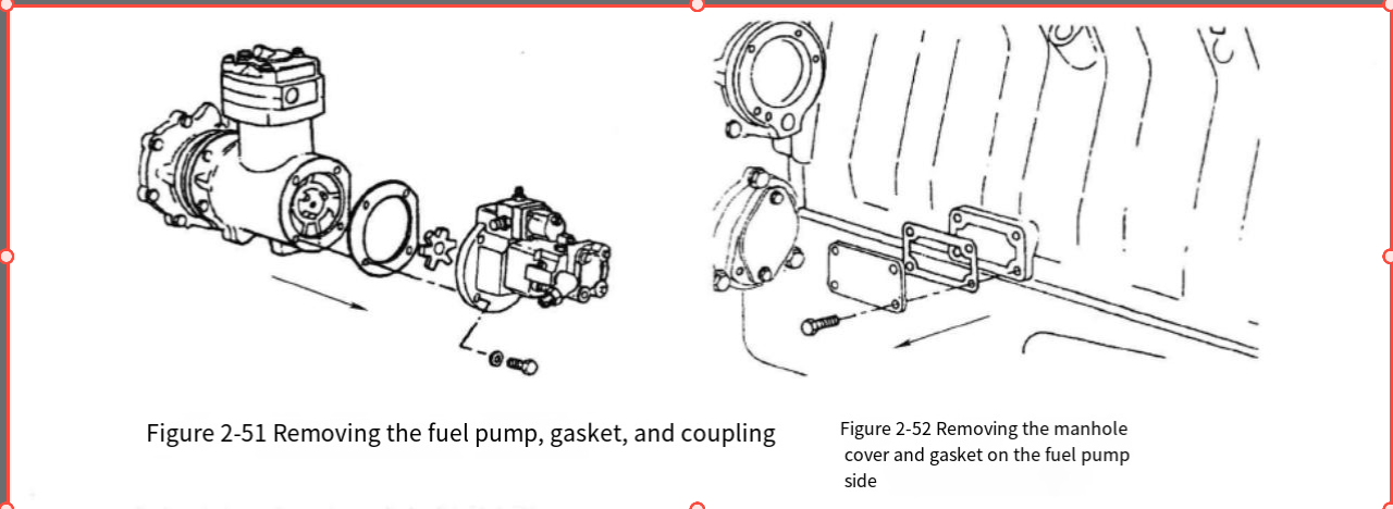
3—Cooling Officer 

 ④ Remove the 4 mounting bolts, fuel pump, sealing gasket and star coupling connected to the fuel pump, see Figure 2-51. 

 ⑤ Remove the inspection hole cover and sealing gasket on the fuel pump side, see Figure 2-52.


 CUMMINGS INPOWER PRO 14.5 Diagnostic Software with 2023.6 PGA by remote installation


  (3) Removal of ECM and ECM cooling plate  

① If an atmospheric pressure sensor is installed on the engine, remove the atmospheric pressure sensor and connecting wires from the front bracket of the ECM, see Figure 2-53. 

 ② Remove the wire harness clamps from positions 1 and 2 on the ECM bracket, loosen the AMP connector mounting bolts on the sensor wire harness, and remove the actuator wire harness and sensor wire harness from the ECM, see Figure 2-54. 

 ③ Remove the ECM mounting bolts, star washer and ECM, see Figure 2-55. 

 ④ Remove the 4 fixing bolts, ECM cooling plate and mounting bracket, see Figure 2-56.


2024年1月20日星期六

How to Remove Cummins M11 Engine thermostat, Torque converter cooling plate, oil cooler and oil filter

 This article mainly introduces how to remove the Cummins M11 engine thermostat, torque converter cooling 

plate, oil cooler and oil filter  

 Cummings Insite 8.7/8.9.2 Pro Diagnostic Software( Support Calibration Online) Download and Installation


① Loosen the coolant hose clamp, and remove the 4 bolts, thermostat housing and thermostat, see 

Figure 2-28. 


② The torque converter cooling plate restricts the flow of coolant through the thermostat housing to the

 water pump bypass hose. This allows the coolant to circulate through the remotely mounted torque 

converter oil cooler. Remove the torque converter cooling plate between the thermostat housing and 

the 

water pump bypass hose joint, see Figure 2-29.


③ Remove the 4 bolts between the oil cooler and the thermostat housing bracket flange, and remove 

the 

4 bolts between the oil cooler and the oil filter seat, the oil cooler and the sealing gasket, see Figure 2

  -30, and remove the oil cooler water inlet pipe, water outlet pipe and mounting flange.

 Cummings INLINE 6 Diagnostic Adapter for Heavy Duty Truck High Quality


④ Remove the Jacobs@ engine brake oil supply pipe, and remove the turbocharger oil return pipe bracket mounting bolts, see Figure 2-31


⑤ Remove 9 bolts, oil filter seat and sealing gasket, see Figure 2-32. Remove the supercharger oil return pipe from the cylinder block.


2024年1月15日星期一

How to Deal with the Alarm and Speed limit of 1400RPM when the Doosan Excavator Engine is Working

This article mainly introduces how to deal with the problem of alarm and speed limit of 1400RPM when the doosan excavator engine is working.


2023.07 Doosan DMS-5 Data Monitoring System Diagnostic Software

Fault phenomenon:

An alarm occurs during engine operation and the speed is limited to 1400RPM. 

 Inspection Method: 

 1) The vehicle has been working for 2200 hours, the equipment speed limit is 1400rpm, and the fault code retrieved is P1251: fuel balance leakage;

2) Check that the low-pressure oil line pressure is 70kpa, which is on the low side (normally around 90kpa); after cleaning the oil-water separator, the low-pressure pressure has increased, but the fault still occurs from time to time;

3) After low-pressure inspection, check the high-pressure system, connect the software to perform cylinder disconnection test and crankshaft acceleration test. There is no obvious abnormality in the working status of each cylinder;

4) Check that the resistance of the IMV valve is 3.2 ohms and is normal. Since the IMV valve is easy to disassemble, the 2018-04-27 13:49 Wang Xiaobo IMVi valve was replaced first and tested. After replacement, the equipment works normally.  

Doosan Diagnostic Tool UVIM Support Doosan Excavators High Quality 

Doosan Diagnostic Tool DDT G2 SCAN( ECU ,DCU)Software 2016

When the P1251 fault code occurs in the engine, the casing should be arranged from simple to difficult. First, check the low-pressure fuel oil line, and then conduct troubleshooting of the high-pressure well rail system.


2024年1月13日星期六

How to Disassemble the Exhaust Manifold and Intake Manifold of Cummins M11 Series Engine

 This Article explains how to disassemble the exhaust manifold and intake manifold of a Cummins M11 series engine.


① The exhaust manifold assembly consists of three sections. When disassembling, remove a bolt from 

the end of each section and then install two guide pins. (Part No. 3376488), remove the remaining bolts, 

and then remove the exhaust manifold, see Figure 2-25. 

Cummings INLINE 6 Diagnostic Adapter for Heavy Duty Truck High Quality 


  ② Remove the intake manifold pressure sensor and temperature sensor wire connectors from the 

intake manifold, see Figure 2-26. 

 Cummings Insite 8.7/8.9.2 Pro Diagnostic Software( Support Calibration Online) Download and Installation

 ③ Remove the intake manifold joint and gasket from the top of the intake manifold, remove the two 

mounting bolts, and install the two guide pins (Part No. 3376488), remove the remaining bolts, and 

install the lifting frame to the rocker arm chamber shell with 4 M10 × 25 bolts. The tightening torque is

 47N·m, see Figure 2-27.

2024年1月10日星期三

How to Replace a Cummins B Series Engines Water Pump

    
How to Replace a Cummins B Series Engines Water Pump

Cummings Insite 8.7/8.9.2 Pro Diagnostic Software( Support Calibration Online) Download and Installation

A Preparatory Steps:
Drain the coolant.

Remove the drive belt.
Remove the two capscrews and water pump, and com-plete the following steps.


Cummings INLINE 6 Diagnostic Adapter for Heavy Duty Truck High Quality

B Clean the sealing surface on the cylinder block.


C  Install the new sealing ring into the pump groove.


CUMMINGS INPOWER PRO 14.5 Diagnostic Software with 2023.6 PGA by remote installation


Install the water pump.Torque Value: 24 Nom [18 ft-lb]


2024年1月3日星期三

How to Remove Cummins M11 Turbocharger and Oil Return Pipe

This article mainly introduces how to disassemble the Cummins M11 turbocharger and the oil return pipe.
 
  ① Remove the oil supply pipe and sealing gasket from the top of the turbocharger, remove the other end 
 
of the oil supply pipe from the oil filter seat, and then remove the oil return pipe and sealing gasket from 
 
the bottom of the turbocharger, see Figure 2-22. 
 
 ② Remove the V-shaped clamp, exhaust elbow and O-ring from the exhaust port of the turbocharger 
 
compressor, remove 4 mounting nuts, remove the turbocharger and gasket, and block the supercharger
 
  For 
 
the oil supply hole and oil return hole, see Figure 2-23. 
 
 
③ Remove the turbocharger oil return pipe joint, see Figure 2-24.


Cummins DD13/15/16 Engine Drive Belt Replacement

This article describes the Cummins DD13/15/16 engine drive belt replacement   Cummings Insite 8.7/8.9.2 Pro Diagnostic Software(Support Cal...