This code is generated when the diagnostic circuitry within PL522 and 523 detects a system voltage higher than 32 VDC. Possible causes of this fault include:
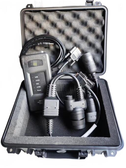
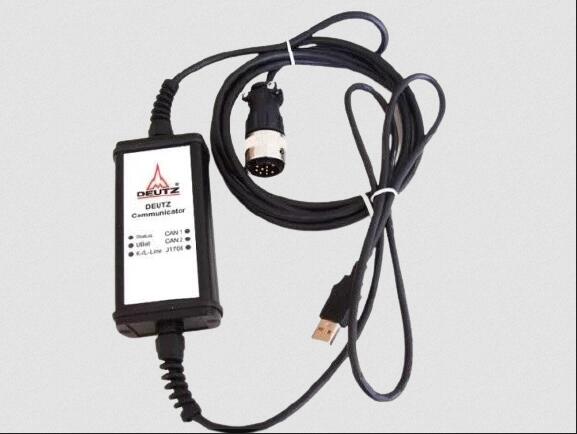
CAT Comm Adapter3 478-0235 Diagnostics for Caterpillar
• A faulty charging system component.
• A faulty wiring harness conductor.
• A faulty PL522 or 523. A module fault is unlikely.
Note: Determine if a battery charger or welding machine is being used on the machine. Disconnect the charger or welding machine from the machine. Recheck for diagnostic codes.
Test Procedure 1. Check the system voltage at the 70-pin connector of PL522 or 523.
A. Start the engine and run it at high idle for 5 to 10 minutes.
B. Measure the system voltage between the "No Switching Power" and "Ground" contacts. Pin 52 is the "No Switching Power" terminal, and pin 65 is the "Ground" terminal.
Caterpillar ET 2026A & 2019C Electronic Technician Diagnostic Software Download and Installation
Expected Result: Voltage is 11 VDC to 32 VDC.
Result: • Normal - Voltage is 11 VDC to 32 VDC. PL522 or 523 should not record this diagnostic code.
Repair: Clear the diagnostic code from PL522 or 523 using a Caterpillar Electronics Technician (Cat ET). If the voltage is normal and PL522 or 523 records this diagnostic code again, replace PL522 or 523. Before replacing PL522 or 523, please contact your Caterpillar technical communicator.
Stop • Abnormal - Voltage is not 11 VDC to 32 VDC. Proceed to Test Step 2.
Test Step 2. Check the alternator.
A. Run the engine at high idle for 5 to 10 minutes.
B. Measure the voltage output at the battery terminals.
Expected result: The voltage should be below 32 VDC.
12.2021 Caterpillar ECM ECU Flash Files Full Set Download
Result: • Normal - Voltage below 32 VDC. The battery may be faulty. Proceed to test step 3.
• Abnormal - Voltage above 32 VDC. Troubleshoot the alternator. The voltage regulator may be faulty. If no issues are resolved, proceed to test step 3.
Test Step 3. Check the battery voltage.
Turn the ignition switch to the off position. Measure the voltage at the battery terminals.
Expected result: The voltage should be below 32 VDC.
Result: • Normal - Voltage below 32 VDC. Proceed to test step 4.
Result: • Yes - Other "CID 168 FMI 00" diagnostic codes can be found on other Electronic Control Modules (ECMs). Repair: Clear the fault if all of the following occur:
Monitor the module and the machine for any further faults. If the fault recurs, the PL522 or 523 module is not faulty because other electronic control modules are displaying the same fault. Recheck the system voltage.
Stop • No - No other "CID 168 FMI 00" diagnostic codes can be found on other ECMs. Repair: Clear the fault if all of the following occur:
◦ No fault was found in the charging system.
◦ No fault was found in the wiring.
◦ The fault has recurred several times.
Monitor the module and machine for further faults. If the fault recurs, the PL522 or 523 module may be faulty. The PL522 or 523 should be replaced. Refer to System Operation, Troubleshooting & Repair, Testing & Adjustment, "Electronic Control Module (ECM) - Replacement". After replacing the PL522 or 523, recheck the system and check the status of the diagnostic codes.
Stop
Caterpillar 18 Digits Factory Password Calculator One-Time Calculate Service