Using DEUTZ diagnostic tools (based on SerDia software and the DECOM interface) to diagnose faults requires following a standardized process: safety preparation → hardware connection → software communication → fault code and data parsing → action testing and calibration → repair verification → report archiving. The core is to differentiate between current and historical faults, combine freeze frames and data streams to pinpoint the root cause, and avoid blindly replacing parts based solely on fault codes.
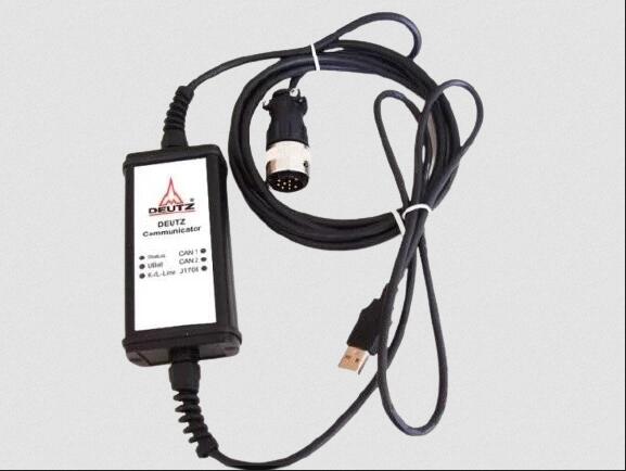
Deutz Diagnostic Tool Communicator for Deutz Engine DECOM Controllers
1. Establishing a connection: Common locations for the diagnostic port: right side panel of the cab, under/behind the seat, near the ECU next to the engine, inside the fuse box; in construction machinery (such as road rollers), it is often located in the footwell or side panel. Interface type: OBD-II (highway vehicles) or DEUTZ dedicated 3-pin/6-pin CAN interface (non-highway equipment).
2. Connection Steps: With the engine off, connect the adapter to the vehicle's diagnostic port;
Connect the adapter's USB end to the computer and open the SerDia software;
Turn the key to the ON position (without starting the engine) to power on the ECU.
3. Establish Communication Select "Diagnostics → Connect ECU" in the software, automatically scan or manually select the protocol (CAN/K-Line); Select the corresponding engine model and ECU (e.g., EMR4 EDC17), and wait for the "Communication Successful" message; If it fails: Check the adapter driver, diagnostic port power/ground, and CAN line termination resistance (approximately 60Ω).
4. Core Diagnostic Process (Key to Fault Location)
Step 1): Read and Classify Fault Codes (DTCs) Enter "Fault Code Management" and read the current fault (Active), historical faults (History), and pending faults (Pending);
2). Record complete information: DTC code (e.g., P0340, SPN+FMI), fault description, number of occurrences, freeze frame (speed, load, temperature, voltage, etc. at the time of the fault);
3), priority principle: handle the current fault first, then analyze historical faults; communication faults (starting with U) take precedence over sensor/actuator faults.
Step 2: Freeze Frame and Data Stream Analysis (Reconstructing Fault Conditions)
2024 Deutz SerDia 4.0 SerDia2010 14.1.9.3 Highest Level 6 Diagnostic Software
5. Freeze Frame and Data Stream Analysis (Reconstructing Fault Conditions)
1) Retrieve freeze frames to confirm the boundary conditions at which the fault occurred (e.g., idle/full load, cold/hot engine, regeneration stage).
2) Enter "Real-time Data" and add key parameter groups for monitoring:
a) Power System: Battery voltage, ECU power supply voltage;
b) Intake System: Intake pressure (MAP), intake temperature, boost pressure;
c) Fuel System: Common rail pressure (actual/target), metering valve opening, injector drive status;
d) Timing System: Crankshaft/camshaft speed, phase deviation;
e) Aftertreatment: NOx sensor, DPF differential pressure, regeneration status;
3) Anomaly Judgment: Compare with standard values (e.g., idle common rail pressure approximately 500–800 bar) and observe whether the parameters change synchronously with the operating conditions (e.g., whether the accelerator pedal opening and fuel injection quantity are linear).
4. Operational Testing and Circuit Verification (Distinguishing Component/Wire/ECU Faults)
1) Check "ECU Information": Software version, hardware serial number, calibration number, and confirm if it is the latest version;
2) Verify key calibrations (such as injector correction codes, idle speed, regeneration strategy). If they do not match the vehicle model, recalibration is required (original manufacturer authorization required).
6. Repair Verification and Fault Code Clearing
1) Repair Implementation: Based on the location results, repair the wiring, replace faulty sensors/actuators, clean or replace filters, update ECU software, etc.;
2) Clear Fault Codes: After repair, go to "Fault Code Management" → "Clear Fault Codes" to confirm that all DTCs have been cleared;


