Figure 1-22 Composition of the BFM1013 diesel engine single pump fuel system 1-Fuel tank; 2-Fuel inlet pipe; 3-Fuel pump; 4-Diesel pipe; 5-Diesel filter; 6-Fuel inlet pipe; 7-Single pump; 8-High-pressure oil pipe; 9-Injector; 10-Injector return pipe; 11-Return oil overflow valve; 12-Return oil pipe; 13-Distance between the inlet and outlet pipes of the fuel tank
(1) Composition of the single pump diesel engine fuel system ① Function Like the ordinary fuel system, the function of the single pump fuel system is to deliver a certain amount of fuel to the combustion chamber of the diesel engine at a certain pressure. ② Composition of the low-pressure oil circuit As shown in Figure 1-22, the single pump fuel system consists of a diesel tank, a low-pressure oil pump, a fuel filter (coarse filter, fine filter), and corresponding oil and other components.Diesel fuel flows from the fuel tank 1, passes through the fuel transfer pump 3, and enters the diesel filter 5. After filtration, it enters the low-pressure oil chamber cast in the cylinder block in non-electronically controlled models. The return fuel also flows into this chamber.The pressure in the low-pressure oil chamber is 0.5 MPa. If the diesel engine experiences insufficient power, the pressure in the low-pressure oil circuit should be measured first.The measurement location is at the external connection of the low-pressure oil circuit. At a diesel engine speed of 2300 rpm, p ≥ 0.45 MPa. ③ High-pressure Oil Circuit: The fuel in the low-pressure oil circuit flows from the unit pump through a short high-pressure oil pipe to the injector. When the pressure reaches 25.0 MPa, the injector opens, spraying the fuel into the combustion chamber in a mist form, where it mixes with air to form a combustible mixture. The oil pressure in the oil circuit from the diesel tank to the low-pressure fuel chamber joint is established by the fuel transfer pump. The oil pressure of the fuel transfer pump at the rated speed of the diesel engine is generally about 0.5MPa. Therefore, this section of the oil circuit is called the low-pressure oil circuit and is only used to supply oil to the single pump.The oil pressure in the oil circuit from the single pump to the injector is established by the single pump and is about 160MPa.④ Fuel return Since the fuel supply of the fuel transfer pump is more than 10 times greater than the oil output of the single pump, a large amount of excess fuel flows back to the diesel tank through the pressure limiting valve 11 and the return pipe 12 (see Figure 1-22). The large amount of return fuel is used to carry away the air in the oil circuit, which has an automatic exhaust function.(2) Use and maintenance of the low-pressure oil circuit system The BFM1013 mechanical single pump diesel engine has two low-pressure oil circuit pressure systems: 0.3MPa and 0.5MPa.① Low-pressure Oil Line Pressure Testing: Stable pressure in the low-pressure oil line is crucial to the diesel engine's power output.If the diesel engine experiences underpower, first check (measure) the pressure in the low-pressure oil line, controlled by the pressure-limiting valve 11 (see Figure 1-22).The primary cause of injector leakage is insufficient low-pressure oil line pressure, leading to cavitation of the injector components.Therefore, ensure the low-pressure oil line pressure and replace or clean the diesel filter promptly.The low-pressure oil line pressure measurement location is shown in Figure 1-23.
Figure 1-23: Low-pressure Oil Line Pressure Measurement Low-pressure oil line pressure limits: 0.3MPa system, p ≥ 0.20MPa (n = 2200 rpm); 0.5MPa system, p ≥ 0.45MPa (n = 2300 rpm). Because the single-pump system requires a high pre-pressure for the fuel, it is necessary to test the fuel system pressure.If the measured pressure is lower than the specified value, the fuel pump and return oil relief valve must be inspected. ② Fuel Pump Flow Check: The fuel pump (Figure 1-24) not only supplies fuel to the injection pump but also cools the fuel system. Therefore, the fuel pump's fuel flow rate is significantly greater than the injection pump's needs.For this reason, this engine uses a diaphragmless rotor-type fuel pump with a fuel flow rate of 12 L/min at a supply pressure of 0.5 MPa. To verify the fuel flow rate, at the return oil line (the oil line after the return oil relief valve), a minimum of 8 L/min of return oil should be observed at maximum idling speed.If the return oil flow rate is lower than this value, the fuel pump must be replaced. ③ Checking the Return Oil Relief Valve: The return oil relief valve (shown in Figure 1-25) establishes a minimum pressure in the low-pressure oil circuit to meet the instantaneous fuel delivery requirements of the injection pump. If the measured pressure is lower than the above value, the return oil relief valve should be replaced, provided that the fuel delivery pump is not faulty. Note: The low-pressure oil circuit pressure of the unit pump is higher, and conventional fuel supply system return oil check valves may not be able to meet the pressure buildup requirements. Therefore, a dedicated unit pump fuel system return oil relief valve must be used.
The BFM1013 diesel engine uses a single pump fuel system.For diesel engines using a single pump fuel supply system, the maintenance and repair of the single pump are completely different from those of traditional diesel engine injection systems, and have many special requirements, which brings a lot of trouble to users and repairers.Due to the special nature of the BFM1013 diesel engine injection system, most of its use and maintenance work revolves around the fuel system. If the maintenance work is not in place, the fuel system will often have problems and cause the diesel engine to malfunction.Therefore, it is very important to master the maintenance points of this diesel engine
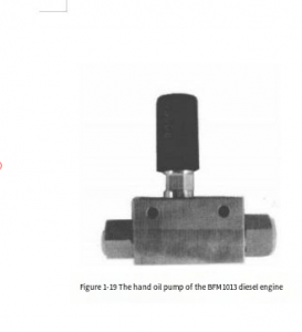
(1) Method for draining the low-pressure oil circuit of the diesel engine The BFM1013 diesel engine fuel system uses a single pump fuel supply system, which has certain special features in removing air from the fuel system.Because unit injection pumps require high fuel pre-pressure, they have two systems: 0.3MPa and 0.5MPa (for a specific diesel engine, only one of these systems may be used). Normally, the pressure should be no less than 0.2MPa (0.3MPa system) and 0.45MPa (0.5MPa system). Therefore, for a 0.5MPa system, the return oil bolt's spring force is much greater than that of an in-line pump, making it difficult to bleed the fuel using a standard hand pump. Improper operation can make it difficult to remove air.Incomplete bleeds may cause difficulty or even failure to start the diesel engine, and may also cause cavitation in the unit pump and pump chamber. ① BFM1013 Diesel Engine Fuel System Bleeding Methods: If a diesel engine fails to start due to air in the fuel system, the following three methods are recommended. a. Before draining, loosen the high-pressure fuel line compression nuts on the injectors and use a hand pump to pressurize and vent fuel until bubble-free fuel flows from all high-pressure fuel lines.Then, tighten the high-pressure fuel line to complete draining. b. Before draining, tighten the high-pressure fuel line nuts on the unit pumps and use a hand pump (Figure 1-19) to pressurize and vent fuel until bubble-free fuel flows from all high-pressure fuel line outlets. Then, tighten the high-pressure fuel line nuts to complete draining. c. Before draining, first loosen the return oil relief valve on the low-pressure fuel chamber, rather than loosening the bleed bolt on the fuel filter as with in-line pumps. Then, pump oil to vent fuel until bubble-free fuel flows. After draining, tighten the return oil relief valve to complete draining. Note: Regularly loosening the high-pressure fuel line to vent fuel is not recommended. Of the above methods for draining, the first one is the most effective, but it's relatively tedious and complex. If you're not familiar with diesel engines, you need to be careful when using it to avoid damaging the valve cover gasket and causing oil leaks.
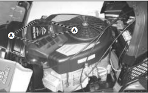
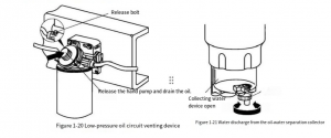
c. Before draining, loosen the return oil relief valve on the low-pressure oil chamber, rather than loosening the bleed bolt on the fuel fine filter as with an in-line pump. Then pump the oil to bleed air until bubble-free fuel flows out. After draining, tighten the return oil relief valve to complete the draining process. Note: Regularly loosening the high-pressure oil line to bleed air is not recommended. Of the above methods for draining, the first one is the most effective, but it's relatively tedious and complex. If you're not familiar with diesel engines, you need to be careful when using it to avoid damaging the valve cover gasket and causing oil leaks. Regardless of the method used to drain the diesel fine filter in the unit pump fuel system of some diesel engines, it is imperative that all air in the fuel system be completely expelled.Otherwise, starting the diesel engine will be difficult. ② Bleeding Methods for Other Unit Pump Diesel Engine Fuel Systems: Some units are equipped with a drain device (indicated by the arrow in Figure 1-20).The draining requirements are as follows.
Figure 1-20 Low-pressure fuel line drain device
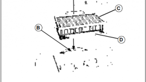
Figure 1-21 Draining the oil-water separator water collector
a. Loosen the bleed plug at the top of the fuel filter and use the hand pump on the coarse filter to drain until the fuel filter is full of fuel and the fuel flowing out of the bleed plug is free of bubbles. Then tighten the bleed plug.
b. Loosen the bleed plug at the top of the unit pump chamber and use the hand pump to drain until the pump chamber is full of fuel and no bubbles are emitted. Then tighten the bleed plug.
c. Loosen the connectors connecting the high-pressure fuel lines to the injectors of each cylinder. Use a hand pump to expel air from the high-pressure fuel lines until fuel flows out. Then tighten the connectors.
d. After draining, wipe clean the fuel flowing out of the diesel engine and the frame before starting the diesel engine. e. It is forbidden to use the starter to drag the diesel engine for draining.
f. During the draining process, avoid splashing the fuel onto the exhaust pipe, starter, wiring harness (especially the connector). If it is accidentally splashed, wipe the fuel clean.
g. During the draining operation, the fuel must be kept clean and free from contamination.
(2) Precautions for the use of the single pump fuel supply system
① Since the single pump injection pressure is high, the quality requirements for the fuel are relatively strict. Therefore, the fuel system of the diesel engine should adopt at least a two-stage filtration system (coarse filtration and fine filtration). If conditions permit, a special oil-water separator filtration system can be installed. ② The fuel should be clean light diesel that meets national standards and must be precipitated and filtered for at least 2 to 3 days.
③ Regularly replace the diesel filter and clean the diesel tank.
④ Regularly drain the diesel coarse filter with oil-water separator, as shown in Figure 1-21.
⑤ During disassembly and maintenance, ensure the work area is clean to ensure a clean installation of the unit pump.
⑥ The unit pump high-pressure fuel line is a single-use component and should generally not be reused after disassembly.
⑦ It is strictly forbidden to disassemble the high-pressure fuel line while the diesel engine is running. Because the pressure within the high-pressure fuel line can reach 180.0 MPa and there is a pressure hold delay, the high-pressure fuel line should be disassembled 1 minute after the engine is shut down.
⑧ If the diesel engine experiences malfunctions such as difficulty starting, insufficient power, or prone to stalling, first inspect the low-pressure fuel line of the unit pump fuel system.
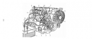
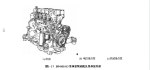
(1) Introduction to the BFM1013 diesel engine. The Deutz BFM1013 diesel engine is an inline engine with two types: four-cylinder and six-cylinder.The biggest structural feature of this diesel engine is the use of a single pump fuel injection system (including two major categories: mechanical control and electronic control), as shown in Figure 1-17.
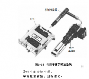
The mechanical single pump diesel engine uses a speed governor to control the speed of the diesel engine. The injector is a common mechanical injector, and the emission index can reach the Euro II standard.The fuel supply time of the electronically controlled single pump is electronically controlled, but the injector is also a common mechanical injector (as shown in Figure 1-18), and the emission index can reach the Euro III standard.The single pump is one of the latest technologies of diesel engines. It makes combustion more suitable for the needs of working conditions, so that the combustion is more complete and efficient, reducing exhaust pollution and fuel consumption.In addition to the above advantages, the single pump system also has the following advantages.① Driven by the camshaft through the tappet, it has a compact structure and good rigidity. ② The injection pressure can reach up to 160.0MPa.
⑤ Good speed regulation performance. ⑥ Has a self-exhaust function. ⑦ Easy maintenance and easy pump replacement. (2) Main parameters of BFM1013 diesel engine The main technical parameters of BFM1013 diesel engine are shown in Table 1-6. ③ Small installation space. ④ The high-pressure oil pipe is short and standardized.
(1) Basic requirements for the first use of diesel engine When a new diesel engine (i.e. new equipment) is put into operation for the first time, the following aspects should be noted. ① Regardless of the length of the original running time of the diesel engine, it is recommended to replace the engine oil and oil filter before it is put into formal use.This is because the brand of the test oil used by the equipment manufacturer may not be the same as the brand of the oil used by the user. To avoid mixing different brands of oil, the engine oil and oil filter (including bypass oil filter or centrifugal filter, etc.) should be replaced before the new equipment is put into use for the first time.
(2) Precautions for starting and stopping the diesel engine ① Preparation before starting.After cleaning the diesel tank and replacing the diesel filter, or when using a new diesel engine or a diesel engine after overhaul for the first time, the fuel system must be vented, otherwise, the diesel engine may not start.
fine filter and use a hand pump to pump diesel until bubble-free diesel flows out of the bleed hole. ② Precautions for starting a diesel engine are as follows: a.Disconnect the working device and ensure the engine starts without load. b. Position the throttle lever to 1/4 of full throttle. c. Start the engine. As soon as the engine ignites, release the start switch immediately.Note: During each start, the starter motor must not operate continuously for more than 10 seconds.If the engine fails to start three times in a row, wait at least 1 minute before starting again. d. After starting the engine, allow it to preheat for at least 3 minutes before operating at full load.During winter operation, the preheating time should be extended (at least 5 minutes). e. After starting, carefully monitor the engine oil pressure.③ Precautions for shutting down a diesel engine.A diesel engine should not be shut down suddenly from full load.Under normal circumstances, it should be idled for 3-5 minutes after unloading, allowing the engine temperature to cool before shutting down.It is best to wait until the oil temperature is below 70°C and the cylinder head temperature is below 80°C before shutting down the engine. In special circumstances, the engine should also be shut down after unloading the engine whenever possible. If a diesel engine suddenly stops while in use (at full load), it is imperative to immediately rotate the crankshaft to prevent residual heat buildup in the engine's moving parts, which can cause problems such as "cylinder scuffing," "shaft seizure," and "burned bearings."
(3) Precautions for winter operation of diesel engines When using a diesel engine in winter, the following points must be noted.
① Winter engine oil must be used.Different brands of winter engine oil should be selected according to the ambient temperature.For details, please refer to the oil selection requirements or the relevant requirements of the instruction manual.
② Use winter fuel.When the ambient temperature is above 0 to 10°C, use 10# diesel.When the ambient temperature is -10 to -30°C, use -30# diesel.When the ambient temperature is below -30°C, use -50# diesel.If the incorrect diesel is used, for example, using 0# diesel at -5°C, wax precipitation from the diesel may clog the filter, causing the engine to malfunction.Therefore, it is essential to use diesel that is appropriate for the ambient temperature.
③ Drain (or clean) the sediment from the fuel tank at least monthly.
④ When the ambient temperature is below -20°C, regularly apply cold-resistant grease to the flywheel ring gear to ensure proper starting.
⑤ When starting a diesel engine in winter, pay special attention to the following points.
a. If the cold start limit temperature is too low, use a preheating device.
b. Ensure the battery is fully charged.
c. Use flame heating plugs.When the ambient temperature is below -25°C, you can use flame heating plugs to preheat and start the diesel engine.To do this: Place the start switch in the preheat position, preheat for 60 seconds, wait for the yellow indicator light to illuminate, and then preheat for another 20-30 seconds before starting the diesel engine.If the engine fails to start successfully once, preheat it for another 1-3 minutes before starting again.Each start should not exceed 10 seconds.
d. When the ambient temperature is below -25°C, the engine must be preheated entirely by other means before starting.For example, hot air generated by a combustion heating device can be used to circulate the engine's internal heat, or the oil in the oil pan can be preheated using a special heating device.
e. When used in winter, the engine should generally not be operated at low temperatures, low speeds (n ≤ 800 rpm), and no load for more than 30 minutes.
f. When starting the engine, avoid operating it at maximum idling speed.
(4) Precautions for diesel engine operation in summer The weather is hot in summer, and the operating environment becomes relatively harsh for air-cooled diesel engines.In order to ensure the normal operation of air-cooled diesel engines in summer, special attention should be paid to the following points.
① The continuous working time of the diesel engine at full load should not exceed 60 minutes. If the operation limit requires continuous operation for a long time, it should be slowed down (n=800~900r/min) after at least 60 minutes and cooled for 3~5 minutes. This can avoid abnormal damage caused by overheating of the diesel engine.
② Select engine oil suitable for summer use according to the ambient temperature. Regularly check the oil quality. If the oil appears black or deteriorates, replace it immediately.
③ Regularly check the operation of the fan system and clean the fan hydraulic coupling regularly; ensure that the fan thermostat and electronic control device are always in good condition.
④ Regularly clean cooling surfaces such as the cylinder liner, cylinder head, and oil radiator to prevent excessive dust accumulation on the cooling surfaces, which may affect the engine's overall heat dissipation efficiency.
⑤ Do not shut down the engine immediately at full load. Run the engine at idle speed (800-900 rpm) for at least 3-5 minutes before shutting down. It is best to wait until the oil temperature is below 70°C and the cylinder head temperature is below 80°C before shutting down.
⑥ If the diesel engine suddenly stops at full load under special circumstances, measures must be taken to prevent "cylinder pulling" or "shaft seizure" failures.
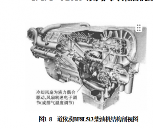
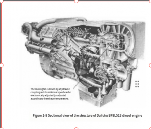
FL513 series air-cooled diesel engine structure introduction Deutz FL513 series diesel engine (as shown in Figure 1-8) marks the beginning of a new era of air-cooled diesel engines.This series of diesel engines uses independent cylinder liners with heat sinks and a one-cylinder-one-head modular structure. The parts are highly versatile and have a wide range of uses.
With the gradual application of electronic technology, the environmental adaptability of diesel engines has gradually increased.Compared with the FL413F series diesel engines, the technical progress of the FL513 series diesel engines mainly includes the following aspects.
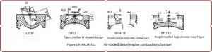
(1) Improvement of combustion chamber The FL513 series air-cooled diesel engines have undergone major changes in the structural shape of the combustion chamber (compared with the FL413F model).The combustion chamber of the non-supercharged model has been improved from an oblique cylindrical (U) combustion chamber to a W-shaped combustion chamber; although the supercharged models all have W-shaped combustion chambers, their structural dimensions have changed significantly, as shown in Figure 1-9.
Through the improvement of the combustion chamber, the diesel engine's combustion system has been improved and the combustion has been more complete, thus greatly improving the various performance indicators of the diesel engine.
①The A-type pump was changed to a P-type pump, which increased the pump oil pressure (the plunger diameter was increased).
②Injector nozzle improvement.The nozzle holes of the non-supercharged diesel engine were changed from 2 holes to 4 holes, and the injection pressure was increased.
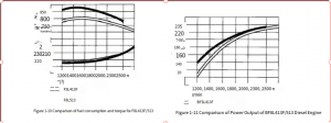
③Reduced fuel consumption and improved torque characteristics, as shown in Figure 1-10.
(3) Improvement of output power
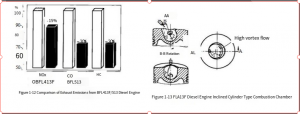
The FL513 model basically retains the basic structural features of the FL413F model: V-type 90° angle, also divided into inline 5, 6 cylinder, V-type 6, 8, 10, 12 cylinder supercharged and non-supercharged models.The turbocharged diesel engine has reduced its rated speed (from 2500r/min to 2300r/min) by improving the combustion mode and the injection pump system, while the non-turbocharged diesel engine has reduced its rated speed (from 2500r/min to 2300r/min) by increasing the cylinder diameter (from 125mm to 128mm), improving the fuel supply system (injection pump) and the combustion mode. The rated power has not only remained unchanged, but also widened the power output range of the diesel engine, thereby greatly improving the adaptability, reliability and service life of the diesel engine.In addition, the overall noise of the diesel engine has also been reduced.The power comparison curve of the BF8L513 and F8L413F diesel engines is shown in Figure 1-11. (4) Improvement of exhaust emission indicators After a series of improvement measures, the exhaust indicators of the FL513 model have been greatly reduced compared with the FL413F model, as shown in Figure 1-12.The emission indicators of the FL513 model have been greatly improved and can meet the requirements of the Euro II standard.
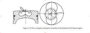
(5) FL413F/513 diesel engine combustion process ① The "D" process of Deutz diesel engine combustion: The axis of the oblique cylindrical combustion chamber (as shown in Figure 1-13) intersects the cylinder centerline at an acute angle.Two oil jets of equal thickness and at an acute angle (28°) are sprayed into the vicinity of the oblique cylindrical combustion chamber wall.The oil jets are blown to the periphery by a strong rotating airflow with an intake tangential velocity of approximately 90 m/s (swirl ratio of approximately 2.6).The oil-air mixture at the center of the combustion chamber has an appropriate concentration and ignites first (the ignition delay period is approximately 2° to 3° crankshaft angle).The oil-air mixture at the combustion chamber wall has a higher concentration and, due to the low temperature, the chemical reaction is controlled and does not ignite immediately.Subsequently, due to the effect of thermal mixing, the combustion gases at the combustion chamber walls flow toward the center. Due to their lower temperature and higher density, the combustion gases at the center are flung toward the chamber walls by the centrifugal force of the swirling vortex, remixing with the denser fuel-air mixture at the chamber walls and further burning. The Deutz "D" combustion process is characterized by low combustion noise, avoidance of combustion shock during startup, reliable startup at ambient temperatures above -15°C, good fuel economy, and low thermal load.The Deutz "D" combustion process is used in the FL413F series non-turbocharged diesel engine. ②Deutz diesel engine combustion "Z" process. The Deutz "Z" process utilizes a W-shaped combustion chamber (as shown in Figure 1-14).Fuel is injected directly into the combustion chamber at high pressure through a four-hole injector.The fuel-air mixture is formed by the axial rotation of the air along the cylinder liner (swirl ratio 1.7 ± 0.2) and the "squeeze turbulence" inherent in the combustion chamber.
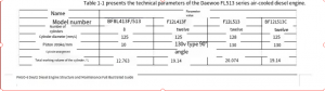
(6) FL513/413F Diesel Engine Main Technical Parameters The FL513/413F series air-cooled diesel engines have a wide variety of models, and only some models are included. Their main technical parameters are shown in Table 1-1.
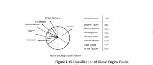
(7) Structural features of FL513 series air-cooled diesel engines ① High degree of standardization, serialization and universalization.The commonality of all engine parts is very high, reaching more than 67% by type and about 85% by number.Whether it is a 6-cylinder engine, an 8-cylinder engine or a 12-cylinder engine, except for the crankcase, crankshaft, camshaft, oil pan, injection pump and intake and exhaust pipes, other parts are universal or basically universal. ② Simple structure and easy maintenance.The one-cylinder-one-head structure facilitates maintenance services such as cylinder pulling, replacement of pistons, cylinder liners and piston rings, and adjustment of valve clearance. ③ Long service life, good reliability and low failure rate.Due to the use of an air cooling system, the failure rate of the cooling system is greatly reduced. Compared with water-cooled diesel engines, the failure rate is reduced by about 34% (as shown in Figure 1-15).The service life can reach more than 10,000 hours.When used on railways or in construction machinery, this series of diesel engines operates at reduced power, with actual operating power at least 10% below rated power. This further extends the engine's service life and significantly reduces the likelihood of engine failure and damage. ④ Low noise and exhaust pollution.This series of diesel engines utilizes advanced combustion theories and noise reduction technologies, resulting in significantly lower noise levels than water-cooled diesel engines of the same power while also significantly reducing emissions.The low-pollution (FL513W) model of this series of diesel engines boasts very high emission standards, making it particularly suitable for use in underground mines and tunnels, and is highly sought after by users. ⑤ Excellent economic performance.This series of diesel engines boasts a fuel consumption rate of 225g/kW·h under rated conditions and a minimum fuel consumption rate of 216g/kW·h, representing oil consumption less than 1% of total fuel consumption.Furthermore, their reliable service life and low failure rate significantly reduce the engine's operating costs, further improving its overall economic performance.⑥ Good power performance and strong adaptability. a. Strong environmental adaptability: Can be used normally in an ambient temperature of -40-50°C.
b. Wide power range (64 to 386 kW), meeting a variety of applications.This series of diesel engines is widely used in trucks, construction machinery, mining machinery, luxury coaches, railway maintenance equipment, and special vehicles. c. The output power of the FL513 series air-cooled diesel engine includes fan power consumption, and its output power is close to the net output power of the diesel engine, thus providing excellent power performance.