This article mainly introduces Removaland Installation of the JCB Backhoe LoaderLoader Arm Safety Strut
10.2022 JCB All ECU’s Modules Flash File Download
Installing
Install the loader arm safety strut as detailed below before working underneath raised loader arms.
AWARNING
Raised loader arms can drop suddenly and cause serious injury. Before working under raised loader arms, fit the loader arm safety strut.
1 Empty the Shovel and Raise the Loader Arms fully.
2 Stop the Engine Remove the starter key.
AWARNING You could be killed or injured if the loader control is accidentally operated. Make sure no-one comes near the machine while you release the safety strut.
2017 JCB Service Parts Pro+Service Repair Download
3 Release the Strut
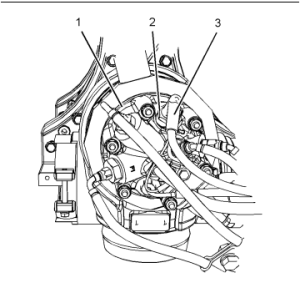
a Release fastener A.
b Remove strut C from its stowage bracket.
4 Install the Strut a Push strut Cover the ram piston rod.
b Secure the strut in position with strap B.

JCB Service Master 4 v22.9.3 [10.2022] Diagnostic Software Download
5 Lower the Strut Onto the Cylinder To prevent any chance of the loader arms creeping down and trapping your fingers, the loader arms should be carefully lowered onto the safety strut as shown.
Start the engine and slowly lower the loader arms onto the safety strut, stop the movement immediately the weight of the loader arms is supported by the safety strut.
Note: When lowering the loader, operate the control lever carefully.' Feather' the lever to lower the loader very slowly.
Removing
1 Fully Raise the Loader Arms To take the weight off the safety strut.
2 Stop the Engine Remove the starter key.
AWARNING You could be killed or injured if the loader control is accidentally operated. Make sure no one comes near the machine while you remove the safety strut.
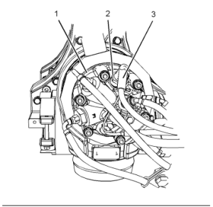
3 Remove the Strut a Undo the strap B.
b Remove the strut C from the ram piston rod.
4 Stow the Strut Secure the strut in its stowage position with fastener A.