This article is about the detailed introduction of Doosan excavator transmission system (1)
Doosan Daewoo Excavator Operation


05 2022 bmw Rheingold ISTA +4.35.20& ISTA -P3.70 With psd2Data FullDownload service

GENERAL
Figure 1, shows layout of power train assemblies. The engine(1, Figure 1) drives a torque converter(2), which drives a power shift transmission (3). Two output shats extend out of the transmission. Each output shaft has a drive shaft attached to it.
Center drive shaft(4) drives a front drive shaft(6) that drives the front differential(7).
A parking brake(8, Figure 1) is mounted on the diferential input shaft. The front differential is enclosed in the front axle housing
(9). Each end of the front axle housing contains reduction gearing(10). Each end of the front axle housing also contains a service brake(11). Rear drive shaft (5) drives the rear differential (12). The rear diferential is enclosed in the rear axle housing(13). Each end of the rear axle housing contains reduction gearing(10). Each end of the front/rear axle housing also contains a service brake(11).


TRANSMISSION AND TORQUE CONVERTER
The machine contains a powershift transmission that has four forward speeds and three speeds in reverse. Gear changes are made by an electrohydraulic control valve that is mounted on transmission. Moving gear select lever in cab, generates an electrical signal that is transmitted to the control valve. The control valve contains proportional valves that direct pressurized fluid to various clutches that control the forward and reverse gears.

The multispeed reversing transmission in layshaft design is engaged under load by hydraulically controlled multidisk clutches.
All gears wheels are constantly meshing and running in antifriction bearings.
The gear wheels, bearings and clutches are cooled and lubricated with oil.
The 4-speed reversing transmission is equipped with 6 multidisk clutches.
At the shifting, the comesponding plate pack is compressed by a piston, movable in axial direction, which is pressurized by pressure oil.
A compression spring is pushing back the piston, thus the releasing the plate pack. As to layout of transmission and the indication of closed clutches in single speeds, See "The Chart of Measuring Points and Connection 4 WG-160"on page-13. and
"Oil Circuit Diagram 4WG-160"on page 1-15.
Transmission Control
Transmission control, See "The Chart of Measuring Points and Connection 4 WG-160"on page-13., Electrohydraulic unit on page-14 and "Oil Circuit Diagram 4WG-160"on page 1-15.
The transmission pump, necessary for the oil supply of converter and the transmission control, is input-side mounted from outside, together with stator shaft and oil supply flange, on transmission. The drive is realized by the pump-wheel flange of converter.
The feed rate of pump is Q=80 lpm at nnwwe=2,000 min".
This pump is sucking the oil through the coarse filter out of oil sump and delivers it through the ZF-Fine filter can be fitted also externally from transmission-to system pressure valve.
ZF-Fine filter Grade of filtration according to ISO 4572:B30 ≥75 B1s=25B1o=
5.0
Fiter area at least:3,700 cm2
Dust capacity according to lSO 4572 at least:17g The six clutches of transmission are selected via the 6
proportional valves P1 to P6.
The proportional valve(pressure regulator unit) consist of pressure regulator (e.g.Y1). follow-on slide and oscillation damper.
The pilot pressure of 9 bar(130.54 psi) for the control of follow-on slides is created by the reducing valve. The pressure oil(16+2 bar(230+29 psi)) is directed through the follow-on slide to corresponding clutch.
By the direct proportional selection with separated pressure modulation for each clutch, the pressure to clutches, taking part in gear change, are controlled. In this way,a hydraulic intersection of clutches to be engaged and disengaged becomes possible. This is loading due to fast shifting without traction force interruption.
At the shifting, the following criteria will be considered:
-Speed of engine, turbine, central gear train and output.
-Transmission temperature.
-Shifting mode(up-, down-, reverse shitting and speed engagement out of Neutral).
-Load condition(full and part load, traction, coasting inclusive consideration of load cycles during the shifting).
These shifting procedures are exactly adapted to different models and types of vehicle.
The system pressure valve is limiting the max. control pressure to 16+2 bar (230 +29 psi) and releases the main stream to converter and lubricating circuit.
A converter relief valve is installed in converter inlet, which protects the converter against high internal pressure(opening pressure 11 bar(160 psi)).
Within the converter, the oil is the medium of power transmission according to well-known hydrodynamic principle.
To avoid cavitation, the converter must be always completely filled with oil.
This is achieved by a converter pressure holding valve, following the converter, with an opening pressure of at least 3.5 bar (51
psi).
The oil, escaping from conveter, is directed to a heat exchanger.
The oil is directed from heat exchanger to transmission and from there to lubricating oil circuit so that all lubricating points are supplied with cooled oil.
In the electrohydraulic control unit there are 6 pressure regulators installed See "Hydraulic Control Unit (HSG-94)"on page 67.
The allocation of pressure regulators to single speeds can be seen on "The Chart of Measuring Points and Connection 4
WG-160"on page 1-13 and "Oil Circuit Diagram 4WG-160?on page 1-15.
The Chart of Measuring Points and Connection 4 WG-160
The measurements have to be carried out at hot transmission
(about 80?95℃).
12.2020 JCB All ECU’s Modules Flash File Download


TRANSMISSION ELECTRICAL
COMPONENTS


1. Sending a control signal transmitted from shift lever to control valve, generates a speed.
2. In auto mode, transmits the appreciate signals to control valves according to load and engine rpm.
3. Detecting a fault, controls various clutches.

1. The transmission control vave contains a temperature sensor and proportional solenoid valves(Y1-Y6) that direct pressurized fluid to various clutches that generates a speed with control the shift gears.
2. Specification of proportional solenoid valve.
Resistance:19 Q?.9 Qat 20℃.
Pressure:0.8kg/cm2>8.3 kg/cm2(11-118 psi)
3. The contained temperature sensor detects the temperature of control valve and transmits the electrical signal to TCU, and serves TCU determines gears to change.
Neutral: At temperature less than-30℃
st or 2nd gear: At temperature less than-10℃
Nomal Operation: At temperature greater than-10?℃
2012 Kobelco Spare Parts Catalog PowerView EPC

1. Detecting a oil temperature of transmission and send a control signal to transmission oil temperature gauge.
2. Specification
Resistance
216Q?0 Q(at 60℃)81.2Q?0Q(at 90℃)
36.5Q?.5Q(at 120℃)
18.7 Q?.1Q(at150℃))

2017 Case Construction EPC Software
Engine Pickup Sensor
1. Detect a revolution of gear array in engine side.
2. Specification
Resistance:10502?0%(at 20℃)
Fasten torque:3.06 kg-m (22 ftlb)
Gap:0.5+0.3mm
(0.0197+0.0118in)
Output:4Pulse/Rev.

Central Gear Pickup Sensor
1. Detect a revolution of central gear array
2. Specification
Resistance:1050Q?0%(at 20℃)
Fasten torque:3.06 kg"m(22ftlb)
Gap:0.5+0.3mm
(0.0197+0.0118in)
Output:91 Pulse/Rev.

1. Detect a revolution of gear array in turbine side.
2. Specification
Resistance:10502?0%(at 20℃)
Fasten torque:3.06 kg"m(22 ftlb)
?Gap:0.5+0.3mm
(0.0197+0.0118 in)
Output59 Pulse/Rev.

Output Speed Sensor
1. Detect a revolution of gear array in transmission o side.
2. Specification
Voltage Supply:20V-32V
Operation Frequency:2Hz-5KHz
Fasten torque(M8):2.3kgrm(17 ft lb)
Gap:1.0-1.5mm
(0.0394-0.0591in)
Output:60 Pulse/Rev.

Shift Lever Switch(DW-3)
Forward, Reverse and Shift
·F: Forward·N: Neutral·R: Reverse
·1.2,3,4: Shit Step
* Forward shift range:1-4
Reverse shift range:1-32. Kick-down(Down Shift) Switch
· KD: Kick-down Switch
3. Lever Lock Key
·N: Neutral(The lever is not moved.)
·D: Driving(The lever is released.)
Switch Circuit

5.Terminal Position and Color

Switch Connection

Forward, Reverse Switch Lever
1. Forward, Reverse Switch
·F: Forward·N: Neutral·R: Reverse
2. Horn Switch
·H: Horn Switch
3. Kick-down(Down Shift) Switch
· KD: Kick-down Switch

Auto Selector Switch
1. This is an auto/manual selector swtch.
2. When the switch is in the 1"-(Auto) position, the gear shifting will take place automatically to be selected by the operator, according to the load and to the vehicle speed.
3. Automatic shifting takes place between gears.
Forward:2nd-3rd-4th
Reverse:2nd-3rd
4. When the switch is in the "0"-(Manual) position, the shifting is retumed to the manual mode and the controlsignal shifts the transmission to gear selected by the operator.

Display
Fault codes are given in a separate section "Transmission Faults Codes".
TRANSMISSION FAULTS CODES
The transmission has a monitoring system that indicates when a malfunction is occurring.
Fault Display If a fault is detected, the display shows a spanner symbol (g) for a fault. The display shows the fault code, if the gear selector is in neutral.
If more than one fault is detected, each fault code is shown for about 1 second.
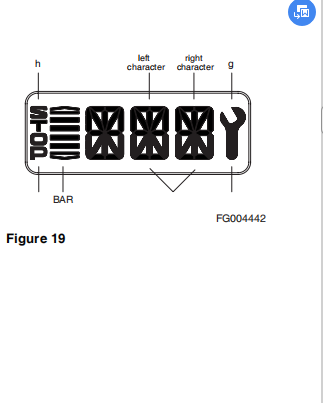
The TCU sends the fault code of a detected fault in the specified CAN-message, while the fault is active.
If more than one fault is detected, the fault code scrolls.
Description of Fault Codes

Throughout this section the following abbreviations are used to indicate various conditions.

2019 Caterpillar Lift Trucks MCFE/MCFA/MCFS EPC+Service All in One VM Version
Definition of Operation Modes
Normal
There is no failure detected in transmission system or failure has no or slight effects on transmission control. TCU will work without or in special cases with little limitations.(see following table)
Substitute Clutch Control TCU cannot change gears or direction under control of normal clutch modulation. TCU uses substitute strategy for clutch control. All modulations are only time controlled.(Comparable with EST25)
Limp-home
The detected failure in the system has strong limitations to transmission control. TCU can engage only one gear in each direction. In some cases only one direction will be possible. TCU will shift the transmission into neutral at the first occurrence of the failure. First, the operator must shift the gear selector into neutral position. If output speed is less than a threshold for neutral to gear and the operator shifts the gear selector into forward or reverse, the TCU will select the limp-home gear. Ifoutput speed is less than a threshold for reversal speed and TCU has changed into the limp-home gear and the operator selects a shuttle shift, TCU will shift immediately into thelimp-home gear of the selected direction. If output speed is greater than the threshold, TCU will shift the transmission into neutral. The operator has to slow down the vehicle and must shift the gear selector into neutral position.
Transmission Shut Down
TCU has detected a severe failure that disables control of the transmission. TCU will shut off the solenoid valves for the clutches and also the common power supply (VPS1).
Transmission shifts to Neutral. The park brake will operate normally, also the other functions which use ADM 1 to ADM 8.
The operator has to slow down the vehicle. The transmission will stay in neutral.
TCU Shut Down
TCU has detected a severe failure that disables control ofsystem. TCU will shut off all solenoid valves and also both common power supplies(VPS1, VPS2). The park brake will engage, also all functions are disabled which use ADM 1 to ADM 8. The transmission will stay in neutral.
Table of Fault Codes
Fault codes are given in a separate section "Transmission Faults Codes".
Measurement of Resistance at Actuator/
sensors and Cable Actuator open circuitR12*R16*R2G * co short cut to ground:R12* R;R1G*0,R2G*R or R1G*R,R2G*
0(for S.C. to ground,G is connected to vehicle ground)
short cut to batter:R12 *R;R1G*0,R2G*R Or R1G*R,R2G*
0(for S.C. to battery,G is connected to battery voltage).

Cable open circuit R12*R1p*R1c *R2p =R2c*0
short cut to ground: R12*0;R1C*PR2c*0,R1p*R2p*0
short cut to battery: R12*0,R1C*R2c *0o,R1p*R2p*0
TRANSMISSION ELECTRICAL
CIRCUITS
T/M Controller Circuit

Figure 22
The transmission proportioning solenoid valves are shown here as (Y1 thru Y6, Figure 27).

Traveling Circuits


没有评论:
发表评论