Translate

2023年3月13日星期一

How to Disassemble Doosan Hydraulic Controller

Disassembly of Doosan DL220 hydraulic controller

Doosan Diagnostic Tool uVIM Support Doosan Excavators High Quality
IMPORTANT:
     Different versions in relation to position of cable harness are possible.
In this connection, pay attention to Specifications of Vehicle
 Manufacturer.


1.
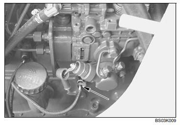
Figure 64, shows complete control unit.


2.
Mark installation position of different covers, housing and cable harness with valve housing.


3.
Remove socket head screws.

Doosan Diagnostic Tool DDT G2 SCAN( ECU ,DCU)Software 2016
4.
Separate duct plate, 1st gasket, intermediate plate and 2nd gasket from valve housing.
(S) Box spanner (Torx TX-27) -5873 042 0025.
Remove retaining clip.


5.
Remove retaining clip.


6.
Remove socket head screws.
7.
Separate cover from housing and cable harness.
(S) Box spanner (Torx TX-27) -5873 042 002


8.
Disassemble opposite cover.
9.
Disconnect pressure regulator and remove cable harness.


10. Remove socket head screws, remove fixing plate and pressure regulators (3x).
(S) Box spanner (Torx TX-27) -5873 042 002


11. Remove two socket head screws and locate housing provisionally, using adjusting screws. (Housing is under spring preload). Remove remaining socket and screws.
(S) Box spanner (Torx TX-27) -5873 042 002
(S) Adjusting screws -5870 204 036


12. Separate housing from valve housing by loosening adjusting screws uniformly.
(S) Adjusting screws -5870 204 036


Doosan DMS-5 (Doosan Data Monitoring System) Diagnostic Software V1.6.3
13. Remove components (Figure 73).
14. Remove opposite pressure regulators, housing and components accordingly (Figure 74).


2023年3月10日星期五

How to Installation the Injection Pump of The New Holland Engine

  Installation of Injection Pump of New Holland_b115 Engine
STEP 1

2023 CASE New Holland Electronic Service Tools (CNH EST v9.7Up3) Engineering Diagnostic Software


Replace gasket on pump mounting flange.


STEP 2


Install pump and tighten the three mounting nuts.


STEP3


Install lock washer and nut, torque nut to 66 to 70
lb-ft (90 to 95 Nm).
WARNING: Use caution when installing nut and
washer they can be dropped inside of the engine.


STEP4


Apply Loctite 5205 to the surface of the cover plate,
install cover plate and mounting bolts, tighten bolts.


STEP 5

Connect wire to temperature sensor.


STEP 6

Connect the fuel feed line to the injector pump.
SECTION 10 - ENGINE - CHAPTER 1 7
Issued 12-04


STEP 7


Remove covers from lines and fittings. Connect fuel
injector lines (1), connect fuel return line (2), and
boost line (3) to the pump. 


STEP 8

CNH DPA5 Adapter New Holland Heavy Duty mechanical Diagnostic Tool


Install oil filler tube (3), mechanical fuel pump (2),
and fuel filter (1) on the engine.


STEP 9


Install the injector line retaining bracket mounting
bolts.


STEP 10

Loosen injector pump locking bolt and install the
slotted plate, tighten the locking bolt to 9 to 10 lb-ft
(12 to 14 Nm).


STEP 11


Make sure locking pin is disengaged from gear.


STEP 12
Remove the engine turning tool and install the
starter.


STEP 13


If the machine has only one battery, connect the
negative battery cable to the battery. Install the
battery cover.


STEP 14


Install grounding cable (2) onto the terminal. Install
the jumper cable (3) on the terminal and start the
terminal nut (1) onto the terminal. Tighten the
terminal nut.


STEP 15


Install the front rocker arm cover and injector line
retaining bracket mounting bolt.


STEP 16


Install the throttle cable into the bracket and tighten
the jam nut.


STEP 17


Install and thighten the two throttle arm mounting
bolts.


STEP 18


New Holland AG& CE Service Manuals PDF 2019Download (170GB)

Connect the power lead to the injector pump.


STEP 19
Actuate the lever on the mechanical fuel pump to
prime the fuel system.


STEP 20
Start the machine and check for fuel leaks, check
and adjust throttle linkage as needed

2023年3月2日星期四

How to Remove the Injection Pump of The New Holland_b115 Engine

 Disassembly of injection pump of new holland_b115 engine

 2022 CASE New Holland Electronic Service Tools(CNH EST v9.6) Engineering Diagnostic Software

 
STEP 1
Secure loader in raised position, (see Operator
Manual), and stop engine.


STEP 2


Remove the battery cover from the right step. If the
machine has only one battery, disconnect the
negative battery cable from the battery, (See
Operator Manual).


STEP 3


If the machine has two batteries, remove the terminal
nut (1). Remove the negative battery cable (2) from
the terminal and move the negative battery cable
away from the battery. Make sure the jumper cable
(3) is installed on the terminal and start the terminal
nut (2) onto the terminal.


STEP 4


Loosen jam nut for throttle cable.


STEP 5


Remove the two throttle arm mounting bolts, move
the throttle cable out of the mounting bracket.


STEP 6


Disconnect the ground strap (1). Disconnect the


STEP 7
Remove the starter from the engine and install
380000988 engine turning tool.


STEP 8


Remove the front rocker arm cover and injector line
retaining bracket mounting bolt. Using engine turning
tool turn engine in direction of running rotation until
push rods can be turned freely.


STEP 9


Have an assistant continue to turn the engine with
turning tool while pressing in on lock pin located just
below injector pump.


STEP 10
Once the lock pin has engaged continue to turn with
light pressure on turning tool until engine has
completely stopped rotating.

New Holland AG& CE Service Manuals PDF 2019Download (170GB)
STEP 11


Loosen injector pump locking bolt and remove the
slotted plate, tighten the locking bolt to 20 to 24 lb-ft
(27 to 33 Nm).


STEP 12


Remove the injector line retaining bracket mounting
bolts.
4 SECTION 10 - ENGINE - CHAPTER 1
Issued 12-04


STEP 13


Remove fuel filter and mounting bracket from engine.

 
STEP 14


Disconnect the power lead to the injector pump.


STEP 15


Disconnect the fuel inlet line from the fuel pump and
fuel return line from the injector pump. Cover line and
fitting to keep foreign material from entering the fuel
system.


STEP 16
Remove the mechanical fuel pump and engine oil
filler tube from the engine.
NOTE: In the following photos the engine is shown
removed from the machine, this is for clarity only, it is
not required to remove the engine.


STEP 17


Loosen fuel injector lines (1), disconnect fuel return
line (2), and boost line (3) at the pump. Cover lines
and fittings to keep foreign material from entering the
fuel system.


STEP 18


Disconnect fuel feed line from injector pump. Cover
line and fitting to keep foreign material from entering
the fuel system.


STEP 19


Disconnect temperature sensor.


STEP 20


Reaching through the inlet hole in the frame, remove
the three plate retaining bolts, remove the plate.
CNH DPA5 Adapter New Holland Heavy Duty mechanical Diagnostic Tool

STEP 21


Loosen and remove nut and washer.
WARNING: Use caution when removing nut and
washer they can be dropped inside of the engine,
engine will have to be disassembled to remove the
nut or washer.


STEP 22


Install gear puller and tighten bolts until gear is loose.

STEP 23


Remove the three mounting nuts from the studs, two
are located at arrows, one is located at the bottom of
the pump. Remove the pump from the engine
6 SECTION 10 - ENGINE - CHAPTER 1
Issued 12-04


2023年2月28日星期二

How to Update a JCB Backhoe Loader Wear Pads (Power Side Shift)

 JCB Backhoe Loader 3CX, 4CX, 214e, 214, 215 217Power Sideshift - Wear Pad Renewal


Inspection (1000 hours)

When the wear pads are worn to 6 mm (0.23 in) or below
they should be replaced.
It is permissible to rotate the top wear pads 180° to prolong
service life, provided the contact surface is more than 6 mm
(0.23 in) thick.
Note: If rotating the wear pad the grease nipples will have to
be swopped over.

2017JCB Service Parts Pro+Service Repair Download
Dismantling

1 Park the machine on firm level ground, engage the
  parking brake and set the transmission to neutral.
  Lower the loader arms to the ground.


2 Set the carriage fully to end of travel A, shown in centre
   position for clarity.


3 Lower the bucket to take the weight off the kingpost.


4 Switch OFF the engine and remove the starter key,
   operate the control levers to vent residual hydraulic
   pressure.


5 Unlock top lock tab B and unscrew nut C.


6 Remove bolt D through the slot in the rail E.


7 Hydraulic clamp F and washer G should remain in
   position.

JCB ServiceMaster4 V23.2.1(02.2023) Diagnostic Software Download andInstallation
8 Remove plate J and wear pad H.
   Assembly


9 Fit wear pad H, plate J and bolt D.


10 Fit new lock tab B and fit nut C.


11 Set the hydraclamp clearance as described in Sideshift
   - Hydraclamp Clearance Setting.


12 Repeat procedure steps 5 to 11 for the bottom clamp.
    The only difference on the bottom clamps is the wear
    pad is on the opposite side of the rail from the top
   clamp so bolt K need not be completely removed.
   Note: If the wear pad is trapped between the rail and
   carriage, lower the bucket to relieve the load on the wear
   pad.


13 Lift the bucket and set the carriage to the opposite end
   of the travel, repeat the procedure for opposite side.


14 When all clamps have been assembled recheck the
    hydraclamp clearance of all clamps

   02.2023 JCB AlIl ECU'S Modules Flash File Download


How to relieve hydraulic pressure in the hydraulic circuit of a CAT excavator.

  How to relieve hydraulic pressure in the hydraulic circuit of 312D2 and 313D2 excavators   Steps to relieve pressure:   Caterpillar ET 202...