Translate

2022年7月28日星期四

Doosan DL220BLOCK VALVE Theory of Operation


This article mainly introduces Doosan DL220BLOCK VALVE Theory of Operation

 Doosan Diagnostic Tool DDT

 The block valve is made up of four bypass check valve C1.

Output from the steering pump passes through the priority valve that is part of the steering cylinder. See the hydraulic schematic.
(Figure 84). This flow then passes out of the steering cylinder and enters the block valve at port EF. This allows output from the steering pump to join flow from the main pump to supply the boom, bucket, and option control valves.

 Doosan DMS-5 (Doosan Data Monitoring System) Diagnostic Software V1.6.3


Doosan Daewoo Excavator Operation and Repair Manual PDF download

2022年7月26日星期二

Introduces Doosan DL220 Power Steering System CLEANING AND INSPECTION

   This article mainly introduces Doosan DL220 Power Steering System  CLEANING AND INSPECTION


Doosan Diagnostic Tool DDT G2 SCAN( ECU ,DCU)Software 2016


1. Install springs in spool slot. See Figure 48. Springs must
be positioned as shown in Figure 49.


2. Position springs so that amount of spring protruding out of
spool is equal on both sides. See Figure 50.


3. Insert spool into sleeve. See Figure 51. Use care so that
sleeve and spool are correctly assembled. The spring slot
in sleeve must align with spring slot in spool. Also, one of
the T shaped slots (A) in the spool must align with one of
the small holes (B) in sleeve. See Figure 52.


4. Center springs in sleeve. See Figure 53.


5. Install seal ring on sleeve. See Figure 54. Burnish seal ring
with a smooth object until seal does not protrude past
diameter of sleeve.


6. Rotate seal ring. See Figure 55. It must rotate freely


7. Turn sleeve 180°. Install cross pin into sleeve and spool.
See Figure 56.


8. Install two thrust washers and thrust bearing over end of
spool. See Figure 57. The sequence of the parts
installation is shown in Figure 58.


9. Oil O-ring and backup ring and then install them on an Oring assembly tool. See Figure 59.


without resistance


10. Insert assembly tool down into bore of steering unit. See
Figure 60


11. Use assembly tool to install O-ring and backup ring into
bore. See Figure 61.


Doosan DMS-5 Diagnostic Software V1.6.3


12. Unbolt housing from stabilizing base. Hold housing in a
horizontal position. See Figure 62. Insert sleeve and spool
into bore.


13. The sleeve will push the O-ring and backup ring into
correct position. See Figure 63.


14. Bolt housing back into stabilizing base. See Figure 64.


15. Insert ball into hole. See Figure 65.


16. Install threaded bushing into hole that ball was placed into.
See Figure 66. Lightly tighten bushing. The top of the
bushing must be lower than the surface of housing.


17. Lubricate O-ring with 20 weight mineral oil and install it in
groove. See Figure 67.


18. Install middle plate onto housing. See Figure 68. Be sure to
properly align plate holes with holes in housing.


19. Lubricate O-ring with 20 weight mineral oil and install it in
groove. See Figure 69.


20. Install distributor plate. See Figure 70. Be sure to properly
align plate holes with holes in middle


21. Install shaft into bore of housing. See Figure 71. Position
slot in shaft to engage cross pin


22. Position rotor so that cross pin is between two teeth as
shown by position of screwdriver. See Figure 72.


23. Lubricate two O-rings with 20 Weight mineral oil and install
them in grooves of cylinder gear. Slide cylinder gear into
position on housing. See Figure 73.


24. Use a bolt to align holes in cylinder gear with bolt holes in
housing. See Figure 74.


25. Install spacer bushing. See Figure 75. Remove bolt that
was installed in previous step (If equipped.).
OSPL 630:1 = 3.8 mm (0.1496 in) (15, Figure 25)
OSPL 800 (16, Figure 25)
OSPL 1000 (16, Figure 25)
NOTE: Refer to parts manual for our unit to determine if
these parts are installed.


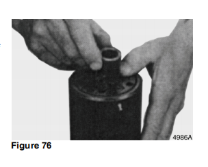
26. Use a screwdriver to install OSPL 800 and 1000 spacers (If
equipped.). See Figure 76.
NOTE: Refer to parts manual for our unit to determine if
these parts are installed.


27. Install end cover. See Figure 77


29. Install six remaining bolts and tighten them. See Figure 79.
Cross tighten bolts and roll pin to 48 Nm (35 ft lb).


28. Install a washer and roll pin into hole shown in Figure 78.


30. Turn steering unit over and work from opposite side. Set
dust seal in position on housing. See Figure 80.


Doosan Daewoo Excavator Operation and Repair Manual


31. Use a seal driver and a plastic hammer to install dust seal.
See Figure 81.


32. Install plastic plugs to prevent dirt from entering steering
unit. See Figure 82.


33. Figure 83, shows port identification for steering unit.
L = Left pressure port.
R = Right pressure port
T = Tank port
P = Pressure from pump.


2022年7月25日星期一

Introduces Removaland Installation of Perkins 2806F Engine Electronic Unit Injector Sleeve

      This article mainly introduces Removaland Installation of Perkins 2806F Engine Electronic Unit Injector Sleeve

Perkins SPI2 VERSION 2018A Service & Parts CATALOGUE

Start By:
a. Remove the electronic unit injectors. Refer to
Disassembly and Assembly, “Electronic Unit
Injector - Remove” for the correct procedure.
NOTICE
Keep all parts clean from contaminants.
Contaminants may cause rapid wear and shortened
component life.
1. Drain the coolant from the engine. Refer to
Operation and Maintenance Manual, “Cooling
System Coolant - Change” for the correct
procedure.


2. Install Tooling (A) in electronic unit injector sleeve
(1).
3. Tighten the nut on Tooling (A) until electronic unit
injector sleeve (1) is pulled free of the cylinder
head.
4. Remove O-ring seals (2) and O-ring seal (3) from
Installation Procedure


Perkins EST Electronic Service Tool Diagnostic Software  2020a
NOTICE
Keep all parts clean from contaminants.
Contaminants may cause rapid wear and shortened
component life.
1. Use Tooling (B) to clean the bore in the cylinder
head for the electronic unit injector sleeve.
NOTICE
Ensure that the electronic unit injector sleeve and the
cylinder head bore are completely free of oil, dirt, and
sealant debris.


NOTICE
Keep all parts clean from contaminants.
Contaminants may cause rapid wear and shortened
component life.
1. Use Tooling (B) to clean the bore in the cylinder
head for the electronic unit injector sleeve.
NOTICE
Ensure that the electronic unit injector sleeve and the
cylinder head bore are completely free of oil, dirt, and
sealant debris.

[04.2022].CLAAS Parts Doc Agricultural Equipment Electronic Spare Parts Catalogue


2. Install new O-ring seals (2) and a new O-ring seal
(3) to electronic unit injector sleeve (1).
Note: Do not apply Tooling (C) to the cylinder head
surfaces. Apply Tooling (C) to the electronic unit
injector sleeve only.
3. Apply a small continuous bead of Tooling (C) to
Surface (X) of electronic unit injector sleeve (1).
4. Lubricate O-ring seals (2) with clean engine oil.
5. Position Tooling (A) and the electronic unit injector
sleeve in the cylinder head. Use care not to
damage the O-ring seals on the electronic unit
injector sleeve.
6. Use Tooling (A) to install electronic unit injector
sleeve (1) in the cylinder head.
Note: Ensure that the electronic unit injector sleeve
is correctly seated into the cylinder head.
7. Remove Tooling (A). Use a clean towel and
remove excess Tooling (C).
8. Fill the cooling system with coolant. Refer to
Operation and Maintenance, “Refill Capacities” for
the cooling system capacity.
End By:
a. Install the electronic unit injectors. Refer to
Disassembly and Assembly, “Electronic Unit
Injector - Install”.

2022年7月21日星期四

Introduces How to Remove and Install Perkins 2806F Engine v>Exhaust Cooler (NRS) l

       This paper mainly introduces how to Remove  and  Install Perkins 2806F Engine v>Exhaust Cooler (NRS) l


Perkins Engine ECM Flash File Download

Removal Procedure
Sulfuric Acid Burn Hazard may cause serious
personal injury or death.
The exhaust gas cooler may contain a small
amount of sulfuric acid. The use of fuel with sulfur levels greater than 15 ppm may increase the
amount of sulfuric acid formed. The sulfuric acid
may spill from the cooler during service of the engine. The sulfuric acid will burn the eyes, skin
and clothing on contact. Always wear the appropriate personal protective equipment (PPE) that
is noted on a material safety data sheet (MSDS)
for sulfuric acid. Always follow the directions for
first aid that are noted on a material safety data
sheet (MSDS) for sulfuric acid.
1. Drain the coolant from the cooling system into a
suitable container for storage or for disposal. Refer
to Operation and Maintenance Manual, “Cooling
System Coolant - Change” for the correct
procedure.


Perkins EST Electronic Service Tool Diagnostic Software Full Function 2020a


2. x
M0070446 23
Disassembly and Assembly Section
Remove bolt (1) from clamp (2). Remove the
clamp and bolts from tube assembly (10).
3. Remove bolt (7) from clip (6). Remove the clip
from tube assembly (10).
4. Remove bolt (14) from clip (15). Remove the clip
from tube assembly (10).
5. Remove bolt (11) from elbow (12). Remove tube
assembly (10) and the elbow from NOx Reduction
System (NRS) exhaust cooler (16) and the water
temperature regulator housing. Remove O-ring
seal (3) (not shown) from the tube assembly.
6. Remove O-ring seal (13) (not shown) from elbow
(12).
7. Loosen hose clamp (5) for hose assembly (4).
8. Sufficiently loosen V-band clamp (9) and remove
tube assembly (8).
9. Remove bolts (23) and bolts (26). Remove elbow
(24), tube assembly (25), and elbow (26) from the
engine oil cooler and NRS exhaust cooler (16).
10. Remove elbow (24) from tube assembly (25).
Remove the tube assembly from elbow (26).
11. Remove O-ring seal (22) (not shown) and O-ring
seal (28) (not shown).
12. Attach a suitable lifting equipment onto NRS
exhaust cooler (16) and support the weight. The
weight of NRS exhaust cooler (16) is
approximately 18 kg (40 lb).
13. Sufficiently loosen V-band clamp (17) and V-band
clamp (19) to allow exhaust bellows (18) to be
removed.
14. Remove bolts (20), clamps (21), and bracket
(16a) from NRS exhaust cooler (16).
15. Use the lifting device to remove NRS exhaust
cooler (16) from the bracket.
16. Remove V-band clamp (17), V-band clamp (19),
and allow exhaust bellows (18)


1. Ensure all components of the NRS exhaust cooler,
tube assemblies are free from wear, damage, and
restriction. Replace any component that is worn,
damaged, or not free from restriction


2. Ensure that clamps (21) are correctly assembled
   with the rounded edges of clamp spacers are
   oriented. Refer to Illustration 36 for the orientation.
3. Attach a suitable lifting equipment onto NRS
  exhaust cooler (16). The weight of NRS exhaust
  cooler (16) is approximately 18 kg (40 lb).
4. Apply Tooling (A) threads of new V-band clamp
  (17) and new V-band clamp (19).
5. Install V-band clamp (17) and a new exhaust
  bellows (18). Ensure that the V-band clamp is
  correctly orientated and the bellows and V-band
  clamp is correctly seated onto the exhaust
  manifold.
6. Loosely install V-band clamp (19) onto exhaust
  bellows (18).
7. Use the lifting device to install NRS exhaust cooler
  (16) onto the bracket. Ensure that V-band clamp
  (19) and exhaust bellows (18) are correctly seated
   onto the NRS exhaust cooler.
8. Install bracket (16a) and loosely install new clamps
   (21) and bolts (20) to NRS exhaust cooler (16).
9. Apply Tooling (B) to both ends of tube assembly
   (25). Install the tube assembly to elbow (24) and
   elbow (26). Ensure that the elbows are correctly
   orientated.
10. Install a new O-ring seal (22) (not shown) and a
   new O-ring seal (28) (not shown) to the engine oil
   cooler and NRS exhaust cooler (16). Ensure that
   the O-ring seals are correctly seated into the
   recesses of the engine oil cooler and the NRS
   exhaust cooler
11. Position the assembly of elbow (24), tube
   assembly (25), and elbow (26) onto engine oil
   cooler and NRS exhaust cooler (16).
12. Install bolts (23) and bolts (26) to the assembly of
   elbow (24), tube assembly (25), and elbow (26).
   Hand tighten the bolts.
13. Install tube assembly (8) and V-band clamp (9).
   Hand tighten the V-band clamp. Tighten hose
   clamp (5) for hose assembly (4).
14. Install a new O-ring seal (13) (not shown) to
   elbow (12). Install a new O-ring seal (3) (not
   shown) to tube assembly (10).
15. Install tube assembly (10) and the elbow to NRS
   exhaust cooler (16) and the water temperature
   regulator housing. Install bolt (11) to the elbow.
   Install clamp (2) and bolt (1).
16. Install clip (6) and bolt (7) to tube assembly (10).
   Hand tighten the bolt.
17. Install clip (15) and bolt (14) to tube assembly
   (10). Hand tighten the bolt.


Perkins SPI2 VERSION 2018A Service & Parts CATALOGUE SOFTWARE


Illustration 37 g06071264
Bolt (1)
Hose clamp (5)
Bolt (7)
V-band clamp (9)
Bolts (11)
Bolt (14)
V-band clamp (17) and V-band clamp (19)
Bolts (20) for the NRS cooler clamps
Bolts (11)
18. Ensure that NRS exhaust cooler (16) is
correctly aligned with the exhaust bellows (18)
before tightening bolts (20) for clamps (21).
19. Follow Step 19.a through Step 19.h to tighten the
bolts and the V-band clamps as listed in Illustration
37 .
a. Tighten bolts (20) to a torque of 40 N·m
 (30 lb ft).
b. Tighten V-band clamp (9) to a torque of 7.5 N·m
 (66 lb in).
c. Tighten hose clamp () to a torque of 7.5 N·m
 (66 lb in).
d. Tighten bolts (11) to a torque of 12 N·m
 (106 lb in)
e. Tighten bolt (1) to a torque of 47 N·m (35 lb ft).
f. Tighten bolts (14) to a torque of 25 N·m
 (221 lb in).
g. Tighten bolt (7) to a torque of 47 N·m (35 lb ft).
h. Tighten V-band clamp (17) and V-band clamp
 (19) to a torque of 7.5 N·m (66 lb in).
20. Fill the cooling system. Refer to Operation and
 Maintenance Manual, “Cooling System Coolant -
 Change” for the correct procedure.


How to relieve hydraulic pressure in the hydraulic circuit of a CAT excavator.

  How to relieve hydraulic pressure in the hydraulic circuit of 312D2 and 313D2 excavators   Steps to relieve pressure:   Caterpillar ET 202...