Translate

2022年7月31日星期日

Introduces Install of the Isuzu Engine 4JJ1 Euro 4 N Series common Rail

     This article mainly introduces Install
of the Isuzu   Engine 4JJ1 Euro 4 N Series common Rail


ISUZU Truck Workshop Service Repair Manual PDF

  1. Install the space rubber, common rail bracket, and common rail, and tighten them at the specified torque.
Tightening torque:25 N-m(2.5kgm/18 b-t)
2. Install the injection pipe and tighten the sleeve nut
(1) at the specified torque.
Tightening torque:25 Nm (2.5 kgm/18 lbt)


3. Install the harness connector of the fuel pressure sensor.
4. Connect the fuel hose(1).


ISUZU Worldwide Snap-on EPC 2018


5. Install the fuel feed pipe(1) and tighten the sleeve nut at the specified torque.
Tightening torque:44 N.m(4.5kgm/33 bt)


6. Install the fuel leak-off pipe(1), and tighten the ayebolt at he specied torque. aC gml e Tightening torque:10 N-m(1.0kg-m/87 lb-in)


ISUZU LinkOne EPC CSS-Net 05.2020


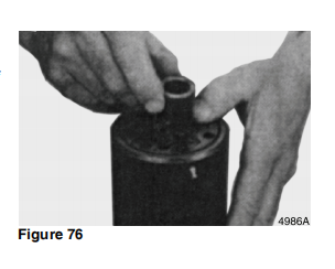
7. Install the engine oil level gauge and guide tube, and tighten the fixing bolt at the specified torque.
· Apply engine oil to the O-ring of the guide tube.
Tightening torque:25 N-m(2.5kg-m/18 ib-ft)
8. Install the left side noise cover.
9. Install the dropping register harness connector.
10. Install the air duct.
NOTE: Firmly insert the hose without any twisting or misalignment, and tighten the clamp to the specified torque.
. Install the air duct between air cleaner and turbocharger.
· Use a new hose clamp, align it with the marking.
Tightening torque Air cleaner side:8 N-m(0.8 kg-m/69 lb-in)
Turbocharger side:6.4 N-m (0.65 kg-m/56.4 lb-in)
NORMA W3 Clamp
8 Nm (0.8 kgm/69 b-in)
NORMA W1 Clamp
11. Install the air intake duct and hose.
List of Tightening Torques

NOTE: Firmly insert the hose without any twisting or misalignment, and tighten the clamp to the specified torque.
· Install the duct and hose between the intake throttle valve and intercooler.
· Use a new hose clamp, align it with the marking Tightening torque:8N-m (0.8kg-m/69 lb in)
12. Connect the connector of the boost sensor.


ISUZU US-IDSS Diagnostic Service Truck Diagnostic System 06.2021


Introduces Removaland of the Isuzu Engine 4JJ1 Euro 4 N Series common Rail


         This article mainly introduces Removaland  of the Isuzu   Engine 4JJ1 Euro 4 N Series common Rail


Legend
1. Injection pipe(#1-#4)5. Common rail(Fuel rail) bracket
2. Fuel feed pipe
3. Injection pipe clip7. Fuel leak-off pipe
4. Common rail(Fuel rail)
Including the inside of the injector, the holes and gaps that are the fuel paths for the fuel system have anextremely precise finish. Therefore, because there is the possibility of damage if foreign material becomes mixed in, cover the cap after removing parts, etc. to prevent the entry of foreign material.
Removal
1. Disconnect the air intake duct and hose.
· Disconnect the boost sensor connector (1), and remove the air intake duct together with the hose.


2. Kemove the air duct(air cleaner-turbocharger alr duct).
3. Remove the left side noise cover.
· Remove the harness connector of the dropping register, and remove the noise cover.
4. Remove the harness connector of the fuel pressure sensor(1).


ISUZU US-IDSS Diagnostic Service Truck Diagnostic System 06.2021


5. Remove the engine oil level gauge and guide tube.
6. Remove the leak-off pipe(1).


NOTE:
Do not reuse the leak-of pipe gasket

7. Remove the fuel feed pipe(1).


ISUZU Worldwide Snap-on EPC 2018 Parts Catalog

ISUZU LinkOne EPC CSS-Net 05.2020


NOTE: Do not reuse the fuel feed pipe
8. Remove the fuel hose(1).
· Keep the disconnected fuel hose in clean, so that dust should not adhere.


9. Remove the sleeve nut(1) of the injection pipe from the common rail.


NOTE: Do not reuse the injection pipe
10.Remove the common rail and the common rail bracket.
NOTE:
·Do not hold the pressure limiter or pressure sensor.
Make sure to hold the common rail unit.
·Be careful not to damage the pressure sensor connector.


ISUZU Truck Workshop Service Repair Manual PDF Download


Legend
1. Common rail(Fuel rail)
2. Common rail(Fuel rail) bracket
3. Space rubber
4. Pressure sensor
5. Pressure limiter

2022年7月29日星期五

Introduces Doosan DL220 The Shut-Off Valve Theory of Operation

 This page briefly introduces Doosan DL220 the shut-off valve theory of operation


Doosan Daewoo Excavator Operation and Repair Manual

Cushion Valve Operation Function The cushion valve absorbs any excessive peak pressure that maybe generated during initial movement of the steering wheel or during a change in steering direction. The cushion valve alsoprevents excessive high-pressure and shock that can result from steering load inertia.
Working Principle If a high-pressure oil is fed back to port R, it pushes spring(3)
and opens poppet(2). This operation directs the high-pressure oil to port L through the center hole in spool(12) and the check valve poppet in port L part. At the same time, oil reaches thepressure room of the plug through orifice (8). This operation closes the passage from port R to port L. This releases the pressure and prevents machine shock by intercepting oil. If a low-pressure oil flows, the cushion operation is not necessary. It is due to the speed of closing spool(12) is faster than the speed of opening poppet (2), therefore, the cushion valve does not work.


Doosan Diagnostic Tool DDT G2 SCAN( ECU ,DCU)Software 2016


Doosan DMS-5 (Doosan Data Monitoring System) Diagnostic Software V1.6.3


2022年7月28日星期四

Doosan DL220BLOCK VALVE Theory of Operation


This article mainly introduces Doosan DL220BLOCK VALVE Theory of Operation

 Doosan Diagnostic Tool DDT

 The block valve is made up of four bypass check valve C1.

Output from the steering pump passes through the priority valve that is part of the steering cylinder. See the hydraulic schematic.
(Figure 84). This flow then passes out of the steering cylinder and enters the block valve at port EF. This allows output from the steering pump to join flow from the main pump to supply the boom, bucket, and option control valves.

 Doosan DMS-5 (Doosan Data Monitoring System) Diagnostic Software V1.6.3


Doosan Daewoo Excavator Operation and Repair Manual PDF download

2022年7月26日星期二

Introduces Doosan DL220 Power Steering System CLEANING AND INSPECTION

   This article mainly introduces Doosan DL220 Power Steering System  CLEANING AND INSPECTION


Doosan Diagnostic Tool DDT G2 SCAN( ECU ,DCU)Software 2016


1. Install springs in spool slot. See Figure 48. Springs must
be positioned as shown in Figure 49.


2. Position springs so that amount of spring protruding out of
spool is equal on both sides. See Figure 50.


3. Insert spool into sleeve. See Figure 51. Use care so that
sleeve and spool are correctly assembled. The spring slot
in sleeve must align with spring slot in spool. Also, one of
the T shaped slots (A) in the spool must align with one of
the small holes (B) in sleeve. See Figure 52.


4. Center springs in sleeve. See Figure 53.


5. Install seal ring on sleeve. See Figure 54. Burnish seal ring
with a smooth object until seal does not protrude past
diameter of sleeve.


6. Rotate seal ring. See Figure 55. It must rotate freely


7. Turn sleeve 180°. Install cross pin into sleeve and spool.
See Figure 56.


8. Install two thrust washers and thrust bearing over end of
spool. See Figure 57. The sequence of the parts
installation is shown in Figure 58.


9. Oil O-ring and backup ring and then install them on an Oring assembly tool. See Figure 59.


without resistance


10. Insert assembly tool down into bore of steering unit. See
Figure 60


11. Use assembly tool to install O-ring and backup ring into
bore. See Figure 61.


Doosan DMS-5 Diagnostic Software V1.6.3


12. Unbolt housing from stabilizing base. Hold housing in a
horizontal position. See Figure 62. Insert sleeve and spool
into bore.


13. The sleeve will push the O-ring and backup ring into
correct position. See Figure 63.


14. Bolt housing back into stabilizing base. See Figure 64.


15. Insert ball into hole. See Figure 65.


16. Install threaded bushing into hole that ball was placed into.
See Figure 66. Lightly tighten bushing. The top of the
bushing must be lower than the surface of housing.


17. Lubricate O-ring with 20 weight mineral oil and install it in
groove. See Figure 67.


18. Install middle plate onto housing. See Figure 68. Be sure to
properly align plate holes with holes in housing.


19. Lubricate O-ring with 20 weight mineral oil and install it in
groove. See Figure 69.


20. Install distributor plate. See Figure 70. Be sure to properly
align plate holes with holes in middle


21. Install shaft into bore of housing. See Figure 71. Position
slot in shaft to engage cross pin


22. Position rotor so that cross pin is between two teeth as
shown by position of screwdriver. See Figure 72.


23. Lubricate two O-rings with 20 Weight mineral oil and install
them in grooves of cylinder gear. Slide cylinder gear into
position on housing. See Figure 73.


24. Use a bolt to align holes in cylinder gear with bolt holes in
housing. See Figure 74.


25. Install spacer bushing. See Figure 75. Remove bolt that
was installed in previous step (If equipped.).
OSPL 630:1 = 3.8 mm (0.1496 in) (15, Figure 25)
OSPL 800 (16, Figure 25)
OSPL 1000 (16, Figure 25)
NOTE: Refer to parts manual for our unit to determine if
these parts are installed.


26. Use a screwdriver to install OSPL 800 and 1000 spacers (If
equipped.). See Figure 76.
NOTE: Refer to parts manual for our unit to determine if
these parts are installed.


27. Install end cover. See Figure 77


29. Install six remaining bolts and tighten them. See Figure 79.
Cross tighten bolts and roll pin to 48 Nm (35 ft lb).


28. Install a washer and roll pin into hole shown in Figure 78.


30. Turn steering unit over and work from opposite side. Set
dust seal in position on housing. See Figure 80.


Doosan Daewoo Excavator Operation and Repair Manual


31. Use a seal driver and a plastic hammer to install dust seal.
See Figure 81.


32. Install plastic plugs to prevent dirt from entering steering
unit. See Figure 82.


33. Figure 83, shows port identification for steering unit.
L = Left pressure port.
R = Right pressure port
T = Tank port
P = Pressure from pump.


Cummins DD13/15/16 Engine Drive Belt Replacement

This article describes the Cummins DD13/15/16 engine drive belt replacement   Cummings Insite 8.7/8.9.2 Pro Diagnostic Software(Support Cal...